3
Preface
Preface
About This Manual
This manual is written for system integrators, IT technicians, and knowledgeable end users.
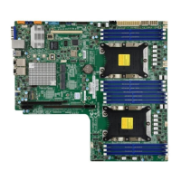
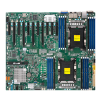
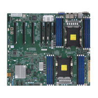
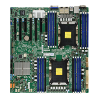
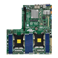
It provides information for the installation and use of the X11DDW-L/NT motherboard.
About This Motherboard
The X11DDW-L/NT motherboard supports dual Intel
®
Xeon Scalable-SP and 2nd Generation
Intel
®
Xeon Scalable-SP series processors (Socket P-F) with a TDP (Thermal Design Power)
of up to 205W and two UPI (UltraPath Interconnect) links of up to 10.4GT/s (Note 1 below).
Built with the Intel
®
C621 built-in (Note 2 below), this motherboard supports up to 3TB of
3DS LRDIMM/RDIMM DDR4 ECC 2933*/2666/2400/2133 MHz memory in 12 memory slots
(Note 3 below). It also supports up to 4TB memory with DCPMM modules. The X11DDW-L/NT
provides maximal system performance, SATA/SAS versatility, and PCI-E expandability. It is
optimized for PCI-Express expansion with exible IO support and is ideal for general-purpose
server platforms. Please note that this motherboard is intended to be installed and serviced
by professional technicians only. For processor/memory updates, please refer to our website
at http://www.supermicro.com/products/.
Note: 1. UPI/memory speeds are dependent on the processors installed in your sys-
tem. 2. The X11DDW-L is supported by the Intel C621 chipset, and the X11DDW-NT
is supported by the Intel C622 chipset. 3. Support for 2933 MHz memory is dependent
on the CPU SKU.
Manual organization
Chapter 1 describes the features, specications, and performance of the motherboard. It also
provides detailed information on the Intel C621/C622 chipsets.
Chapter 2 provides hardware installation instructions. Read this chapter when installing the
processor, memory modules, and other hardware components into the system.
Chapter 3 describes troubleshooting procedures for video, memory, and system setup stored
in the CMOS.
Chapter 4 includes an introduction to the BIOS and provides detailed information on running
the CMOS Setup utility.
Appendix A provides BIOS Error Beep Codes.
Appendix B lists software program installation instructions.
Appendix C lists standardized warning statements in various languages.
Appendix D contains UEFI BIOS Recovery instructions.
 Loading...

