Do you have a question about the Supermicro X11DPG-QT and is the answer not in the manual?
Provides information for the installation and use of the X11DPG-QT motherboard.
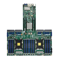
Details the X11DPG-QT motherboard's support for Intel Xeon Scalable-SP processors and memory.
Outlines the structure and content of the manual's chapters and appendices.
Provides contact information for Supermicro's main office location.
Lists contact details for Supermicro's European operations.
Provides contact information for Supermicro's Asia-Pacific region.
Lists the main parts included with the Supermicro motherboard package.
Provides links to download drivers, utilities, and product manuals.
Details the motherboard's compatibility with Intel Xeon Scalable-SP processors and the Intel C621 chipset.
Describes the motherboard's health monitoring capabilities via the ASPEED AST2500 BMC.
Explains the system health monitoring features supported by the onboard Baseboard Management Controller (BMC).
Defines ACPI as a standard interface for integrating power management features across hardware and OS.
Emphasizes the necessity of a stable power source for reliable operation and processor performance.
Details advanced power management features like Intel Intelligent Power Node Manager and Management Engine.
Introduces Intel Optane DC Persistent Memory technology for enhanced data persistence and lower latency.
Covers precautions and unpacking procedures for handling static-sensitive components.
Provides step-by-step instructions for physically mounting the motherboard into a chassis.
Details the process of installing the CPU and its associated heatsink module onto the motherboard.
Explains memory compatibility, population guidelines, and installation procedures for DIMM modules.
Details DDR4 memory capacity and speed support for Intel Xeon Scalable-SP processors.
Outlines DDR4 memory support specifics for 2nd Gen Intel Xeon Scalable-SP processors.
Provides guidelines for populating memory modules to achieve optimal system performance.
Presents a table detailing memory population sequences for various CPU and DIMM configurations.
Provides tables for dual and quad rank memory sparing configurations.
Describes the step-by-step process for inserting DIMM modules into the motherboard memory slots.
Explains how to safely remove DIMM modules from the motherboard memory slots.
Identifies and describes the various input/output ports located on the motherboard's rear panel.
Details the header pins for chassis front panel buttons and indicators.
Describes the various internal connectors on the motherboard, including power and headers.
Details the 4-pin fan headers and their compatibility with 3-pin fans.
Explains the function of the internal speaker/buzzer for audible beep codes.
Describes the Serial General Purpose Input/Output header for enclosure management communication.
Explains the DOM power connectors used for solid-state DOM storage devices.
Describes the Trusted Platform Module/Port 80 header for security and authentication.
Explains the chassis intrusion header for security alerts via IPMI.
Details the 4-pin BMC External I2C header for IPMI 2.0 system management.
Describes the Power System Management Bus (I2C) header for monitoring power and temperature.
Details the motherboard's SATA 3.0 ports and their support for Supermicro SuperDOMs.
Explains the VROC RAID Key header for NVMe RAID support.
Describes the 10-pin audio header for onboard sound chip functionality.
Explains the SPDIF_IN header used for digital audio connections.
Details the NVMe SMBus headers used for hot-plug support and VPP for NVMe add-on cards.
Describes the standby power header location and pin definitions.
Explains the general purpose I/O header for Thunderbolt add-on cards.
Details the M.2 connector for high-speed NVMe SSD cards.
Describes the NC-SI header for network sideband interface for remote management.
Explains the inlet sensor header for BMC to monitor thermal inlet temperature.
Explains the function and configuration of motherboard jumpers for system operation.
Describes the status and meaning of the various LEDs present on the motherboard.
Provides systematic steps to diagnose and resolve system issues.
Guides users on steps to take before contacting technical support for assistance.
Details the correct procedures for removing and installing the motherboard's CMOS battery.
Addresses common user questions regarding motherboard support and BIOS operations.
Outlines the process and requirements for returning products for warranty service.
Introduces the AMIBIOS™ Setup utility for the X11DPG-QT motherboard and BIOS upgrading.
Guides the user on how to access and navigate the BIOS Setup Utility interface.
Details the options available on the main BIOS setup screen, including system date and BIOS information.
Covers various advanced system settings and configurations accessible through the BIOS.
Explains how to configure and manage system event logs within the BIOS.
Provides instructions for configuring Intelligent Platform Management Interface (IPMI) settings.
Outlines the security settings available in the BIOS, including password and secure boot configurations.
Details the BIOS settings related to system boot order and boot mode selection.
Explains how to save BIOS configuration changes or discard them and exit the setup utility.
Lists BIOS beep codes and their corresponding error messages for POST diagnostics.
Provides information on additional checkpoint codes documented online for AMI BIOS POST.
Guides users through the process of installing the Windows OS, including RAID configuration.
Details how to download and install necessary drivers and utilities from the Supermicro website.
Describes SuperDoctor 5, a program for system health monitoring and management.
Explains the support for Intelligent Platform Management Interface (IPMI) for remote access and management.
Guides users on how to log into the BMC using the provided password.
Provides warnings and instructions regarding safe battery replacement and disposal.
Offers guidance on the proper disposal of the product according to national laws and regulations.
Provides an overview of UEFI and its role in the pre-boot environment for OS loading.
Explains the process of recovering the UEFI BIOS image from a recovery block when the main BIOS is corrupted.
Details the steps for recovering the main BIOS block using a USB-attached device.
Guides users on accessing the All Intel VMD Controllers menu for enabling PCI slots for VMD support.
Provides step-by-step instructions for configuring RAID settings for NVMe devices using VROC.
Describes the use of a journaling drive for RAID5 volumes to mitigate data loss from power or drive failures.
Guides the user to set the boot mode select to UEFI for secure boot functionality.
Explains how to configure Secure Boot, Secure Boot Mode, and CSM Support features in the BIOS.
Provides steps to ensure secure boot support by setting specific BIOS configurations.
Details the configuration of key management settings for secure boot when the mode is set to Custom.
Covers PCIe/PCI/PnP configuration settings relevant for network interface card setup.
Details the configuration steps for iSCSI settings, including initiator name and network parameters.
Describes the configuration of onboard Intel LAN devices via the BIOS Setup utility.
| PS/2 ports quantity | 0 |
|---|---|
| IPMI LAN (RJ-45) port | Yes |
| USB 2.0 ports quantity | USB 2.0 ports have a data transmission speed of 480 Mbps, and are backwards compatible with USB 1.1 ports. You can connect all kinds of peripheral devices to them. |
| USB 3.2 Gen 1 (3.1 Gen 1) Type-A ports quantity | 2 |
| Number of SATA III connectors | 10 |
| Number of DIMM slots | 16 |
| Maximum LRDIMM memory | 2000 GB |
| Supported RDIMM module capacity | 64GB |
| Memory voltage | 1.2 V |
| Supported memory types | DDR4-SDRAM |
| Supported memory clock speeds | 2133, 2400, 2666 MHz |
| BIOS type | AMI |
| ACPI version | 4.0 |
| BIOS memory size | 64 Mbit |
| RAID levels | 0, 1, 5, 10 |
| Wi-Fi | No |
| LAN controller | Intel® X550 |
| Ethernet interface type | 10 Gigabit Ethernet |
| On-board graphics card model | Aspeed AST2500 |
| Bundled software | Intel Node Manager, IPMI2.0, KVM LAN, NMI, SPM, SSM, SUM, SuperDoctor 5, Watchdog |
| Storage temperature (T-T) | -40 - 70 °C |
| Operating temperature (T-T) | 10 - 35 °C |
| Storage relative humidity (H-H) | 5 - 95 % |
| Operating relative humidity (H-H) | 8 - 90 % |
| Supported QPI | 10.4 GT/s |
| Processor socket | LGA 3647 (Socket P) |
| Processor manufacturer | Intel |
| Processor number of cores supported | 28 |
| Component for | Server |
| Motherboard chipset | Intel® C621 |
| Audio output channels | 7.1 channels |
| PCI Express x16 (Gen 3.x) slots | 6 |
| Depth | 335.3 mm |
|---|---|
| Width | 384 mm |