44
Super X11SSQ/-L/-V User's Manual
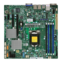
2.7 Connectors
Power Connections
Main ATX Power Supply and 12V DC Power Connector
The primary power supply connector (JPW1) meets the ATX SSI EPS 24-pin specication.
You must also connect the 4-pin (JPW2) 12V DC power connector to your power supply.
ATX Power 24-pin Connector
Pin Denitions
Pin# Denition Pin# Denition
13 +3.3V 1 +3.3V
14 -12V 2 +3.3V
15 COM 3 COM
16 PS_ON 4 +5V
17 COM 5 COM
18 COM 6 +5V
19 COM 7 COM
20 Res (NC) 8 PWR_OK
21 +5V 9 5VSB
22 +5V 10 +12V
23 +5V 11 +12V
24 COM 12 +3.3V
Required Connection
1
10
4
1
1
X11SSQ
REV: 1.01
DESIGNED IN USA
Tested to Comply
With FCC Standards
FOR HOME OR OFFICE USE
BIOS
LICENSE
J23
JPW2
B3
JP7
SP1
LED1
COM3
JSTBY1
JD1
FAN3
FAN4
FAN1
FAN2
JPME2
JWD1
JLED1
JI2C2
JI2C1
JPL2
JPAC1
JPL1
JPW1
JL1
I-SATA5
I-SATA2
I-SATA4
I-SATA1
I-SATA3
I-SATA0
JF1
JBT1
I-SGPIO2
JSD1
JTPM1
COM4
JVR1
I-SGPIO1
LED3
JSMB1
MAC CODE
BAR CODE
COM2
COM1
JAT1
GP7
GP6
GP5
GP4
GP3
GP2
GP1
GP0
AUDIO FP
USB6/7
PCH SLOT4 PCI-E 3.0 X4
PCH SLOT5 PCI-E 3.0 X4
PCH SLOT6 PCI-E 3.0 X1
USB10/11(3.0)
HD AUDIO
CPU SLOT7 PCI-E 3.0 X16
DIMMA2
DIMMA1
DIMMB1
DIMMB2
UNB NON-ECC DDR4 DIMM REQUIRED
ALWAYS POPULATE BLUE SOCKET FIRST
M.2 PCI-E 3.0 X2
LAN2
USB2/3
USB8/9(3.0)
LAN1
HDMI/DP
CPU
DVI-D
CPU FAN
KB/MOUSE
USB0/1
USB4/5
CATERR_LED
J18
1. 24-Pin ATX Main Power
2. 4-pin 12V DC Power
1
2
4-pin 12V Power
Pin Denitions
Pin# Denition
1 - 2 Ground
3 - 4 +12V
 Loading...