44
X11SSV-M4F User's Manual
JF1
JPW1
JPW2
JTPM1
JSD1 JSD2
X11SSV-M4F
REV:1.00
DESIGNED IN USA
FAN2
FAN1
FAN3
JP1
BT1
I-SATA4
I-SATA3
I-SATA2
I-SATA1
JPCIE1 x16
1
J17
JL1
J16
1
JSMB1
JD1
JPG1
JPAC1
JI2C1
JI2C2
JWD1
JVRM1
JVRM2
JPUSB1
JBR1
JPME1
JGPIO1
I-SGPIO1
1
SRW1
SRW3
JPI2C1
A
LED2
C
LED1
A
SRW2
JBT1
JIPMB1
CPU
NIC3
FF
PWR
FAIL
AUDIO
1-2:ENABLE
2-3:DISABLE
JPAC1:AUDIO
SATA DOM
+POWER
DVI-A
JI2C1/
1-2:ENABLE
JWD1:
JSMB1:SMBus1
2-3:DISABLE
1-2:RST
WATCH DOG
2-3:NMI
M.2
JI2C2:
USB7/8
USB5/6
JPUSB1:
USB0/1 WAKE UP
1-2:ENABLE
2-3:DISABLE
JD1:
4-7:SPEAKER
1-2:NORMAL
JPME1:
1-3:PWR LED
JBR1
1-2:NORMAL
RECOVERY
2-3:ME
RECOVERY
2-3:BIOS
PWR
LED
LAN3/4
LAN1/2
m-PCIE
NIC
HDD
LED
NIC
2
1
DIMMA1
DIMMB1
OH
PWR
ON
RST
KB/MS
USB3/4
USB1/2
USB9
COM1
SRW4
Aspeed
AST2400
Intel
I350-AM2
Intel
CM236
1
1. Mini-PCIe
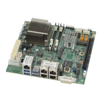
Mini PCI-E Slot (Mini PCIE)
The Mini PCI-E slot is used to install a compatible Mini PCI-E device. Refer to the table below
for pin denitions.
The mSATA feature leverages the speed and reliability of the SATA interface to provide a high
performance, cost-effective storage solution for smaller devices like notebooks and netbooks.
The specication maps SATA signals onto an existing small form factor connector, enabling
more compact integration in a wide variety of applications for both hard disk (HDD) and solid
state drives (SSDs). The mSATA connector allows companies to increase the storage offerings
of their products without compromising valuable space.
Mini PCI-E
Pin Denitions
Pin# Denition Pin# Denition
52 +3.3Vaux 51 NC
50 GND 49 NC
48 +1.5V 47 NC
46 NC 45 NC
44 NC 43 NC
42 NC 41 +3.3Vaux
40 GND 39 +3.3Vaux
38 USB_D+ 37 GND
36 USB_D- 35 GND
34 GND 33 PETp0
32 SMB_DATA 31 PETn0
30 SMB_CLK 29 GND
28 +1.5V 27 GND
26 GND 25 PERp0
24 +3.3Vaux 23 PERn0
22 PERST# 21 DET_CARD_
PLUG
20 W_DISABLE# 19 NC
18 GND 17 NC
16 NC 15 GND
14 NC 13 REFCLK+
12 NC 11 REFCLK-
10 NC 9 GND
8 NC 7 CLKREQ#
6 1.5V 5 NC
4 GND 3 NC
2 3.3Vaux 1 WAKE#
 Loading...

