Do you have a question about the Supero SAS 815TQ and is the answer not in the manual?
Measures to prevent damage from electrostatic discharge (ESD) when handling electronic components.
Important safety procedures for installing or removing system components and cables.
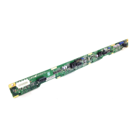
Advises that hardware diagrams may differ from actual components due to PCB revisions.
Identifies and lists the various front-side connectors and jumpers on the SAS backplane.
Provides detailed pin assignments for front connectors, including power, JTAG, and management chips.
Details the physical locations and functions of front jumpers for configuration and reset operations.
Describes rear SAS/SATA connectors and the corresponding activity and failure LED indicators.
| Chipset | Intel C612 |
|---|---|
| Maximum Memory | Up to 512GB |
| SAS Ports | 8 |
| SATA Ports | 8 |
| Processor Support | Intel Xeon E5-2600 v3/v4 |
| CPU Socket Type | LGA 2011-3 |
| Memory Type | DDR4 |
| Storage Bays | 8 |
| Storage Interfaces | SAS 12Gb/s, SATA 6Gb/s |
| Network Interface | Dual Gigabit Ethernet |
| LAN Ports | 2 |
| LAN | Intel i350 |
| PCIe 3.0 x16 Slots | 2 |
| IPMI | Yes |
| Audio | No |