NOTE
- Before installation, please confirm the Wi-Fi signal is strong enough.
- Wi-Fi range can be affected by obstructions, metal objects, distance
and weather. Mount unit should be as close to the router as possible.
- Install upright, in a vertical orientation.
- Always close the rainproof door after use.
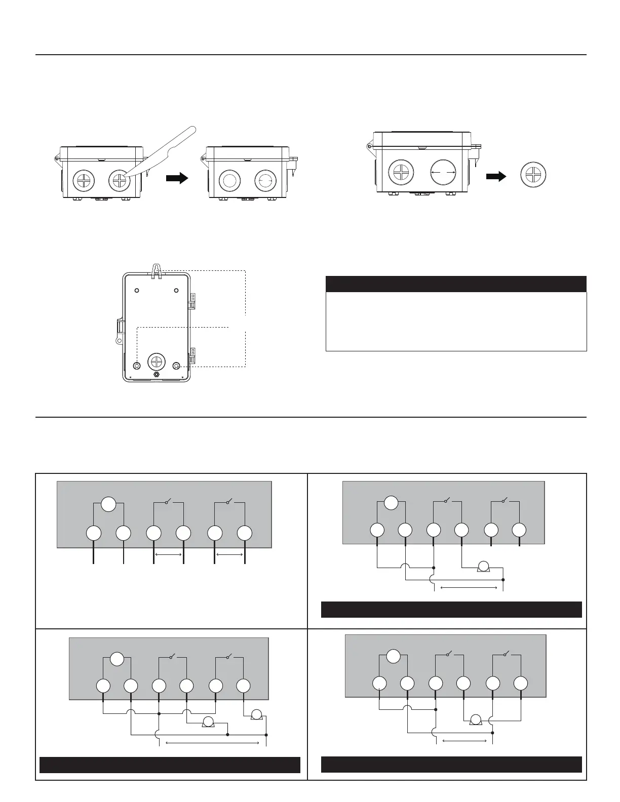
Installation
Connecting the Wires
1. Choose the knockouts (five 1/2’’ to 3/4’’ combination knockouts available)
2. Mounting the Smart Box Timer
For 1/2’’ Knockouts: Carefully cut off the inner ring of the rubber plug with a knife (FIG.2).
For 3/4’’ Knockouts: Please remove the entire rubber plug (FIG.3).
a. Hold the box in place and use the three holes (FIG.4) to mark position on the mounting surface.
b. Mount the box with the screws
1. Lift the plastic insulator off the retaining post to expose the terminal strip.
2. According to the wiring diagram (TYPICAL APPLICATION WIRING DIAGRAMS) to wire.
Note: please connect the grounded wire to the grounding terminal.
L = Line | N = Neutral | NO = Normally Open |
COM = Common Terminal | J = Jumper Wire | T = Timer
FIG6. 120V Application- Controlling One 120VAC Load
Mounting the Smart Box Timer
FIG.2 1/2" knockout FIG.3 3/4" knockout
FIG.4 Mounting Holes
FIG.5 TERMINAL DESIGNATIONS
Mounting Hole
SMART BOX
T
L
L
N
N
S1
Normally Open
(Isolated Contact)
NO1
COM1
S2
Normally Open
(Isolated Contact)
NO2
COM2
SMART BOX
T
L N
S1
120VAC
LOAD
(J1)
L N
NO1
COM1
S2
NO2
COM2
SMART BOX
T
L N
S1
120VAC
LOAD
1
2
(J1)
L N
NO1
COM1
LOAD
S2
NO2
COM2
SMART BOX
T
L N
S1
120VAC
LOAD
(J1)
(J2)
L1 L2
NO1
COM1
S2
NO2
COM2
3/4"
1/2"
FIG7. 120VAC Application - Controlling Two 120VAC Loads
FIG8. 240VAC Application- Controlling One 240VAC Load
2
 Loading...