Size: 18.2 x 25.6 cm (LxW)
3
1
2
3-Year Warranty
The manufacturer warrants to the original consumer /
purchaser free from defects in materials or workmanship
for limited time from the original factory shipment date.
KEEP THIS STUB FOR YOUR RECORDS
Model: Serial :
Date Purchased:
Where Purchased:
From Whom:
MANUFACTURER DISTRIBUTOR
SURECOM
3-Year Warranty
TO:
ATTN:
WARRANTY REGISTRATION CARD
Please complete this form and return it within 10 days of
purchase to validate warranty
Name/Title:
Company:
Address:
Tel. No.: Signature:
Purchase Model: Serial No.:
Purchase from:
Address:
Date of Purchase:
Place
Stamp
Here
"1
"1
Features Overview
•
IEEE 802.3 10BASE2 / 10BASE-T compliant
•
EP-508: eight 10BASE-T ports
•
EP-508T: one BNC port and eight RJ-45 ports
•
Either the RJ-45 or BNC port as the cascading
port
•
Port auto-partitioning and reconnection to
faciltate faulty segment isolation
•
Polarity auto-detection and auto-correction for
UTP/STP ports
•
Data collision and jabber handling functions
•
Two LEDs per port to indicate Link/Receiveand
Partition status
•
LEDs to indicate Power and Collision status
3. Link/Receive (GREEN) Indicators
These LEDs indicate the state of the data link.
The LED remains on when the connection is OK.
These LEDs blink to indicate data is being received
on the segment.
4. Partition (RED) Indicators
These LEDs light to indicate a port on the hub is
malfunctioning. Faulty ports are automatically
isolated by the hub. When the port recovers,
however, the partition LED returns to normal status.
Package Contents
•
One EP-608/EP-608ST Hub
•
One AC Power Adapter
•
One BNC T-Connector (for EP-508T only)
•
This Users' Guide
•
Four Pieces of Rubber Foot
•
Two Pieces of Self-Tapping Screw
•
Two Pieces of Anchor Screw
Panel
The illustrations that follow depict the various exter-
nal components of the hub.
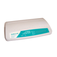
Figure 1: EP-508 Front Panel
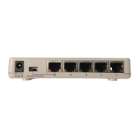
1. RJ-45 UTP/STP Ports
The hub is equipped with 8 RJ-45 UTP/STP ports
for making 10BASE-T hub-to-workstation
connections.
2. Cascade Enable Slide-Switch
Slide this switch to the right to enable cascading
with straight UTP/STP cable.
3. AC Adapter Port
Plug the AC adapter jack into this port.
4. BNC Port (For EP-508T only)
The hub is equipped with one BNC port for
making 10BASE2 hub-to-workstation connections.
Wall Mounting
After you have decided on a suitable location for
mounting the hub, mark the location for inserting two
screws 165mm apart. At the marked locations, drill
two holes and insert an anchor screw in each hole.
Insert a self-tapping screw in each hole. Align wall-
mount slots of the hub with the screws and slide the hub
down until the screws are securely fastened to the hub.
You can now complete the installation procedure by
marking the necessary cable connections.
1. Power (RED) Indicator
When the power LED is lit it indicates that the
hub's power is on.
2. Collision (YELLOW) Indicator
This LED indicator blinks when the hub detects a
collision on the network.
Figure 2: EP-508T Front Panel
Figure 3: EP-508 Rear Panel
Figure 4: EP-508T Rear Panel