EasyManua.ls Logo

Suspa MOVOTEC - User Manual

Suspa MOVOTEC
34 pages
Print Icon
To Next Page IconTo Next Page
Loading...
MOVOTEC
®
Dual-Drive “Bolt-On”
Lift System Manual
by
Copyright © 2013 by
Suspa
®
Incorporated
All rights reserved. No part of this manual may be reproduced or transmitted
in any form or by any means, electronic or mechanical, including photocopying,
recording, or by any information storage and retrieval system
without permission in writing from Suspa
®
Incorporated.

Other manuals for Suspa MOVOTEC

Questions and Answers

  • D
    Darren JacksonAug 16, 2025
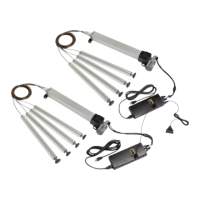
    Why is the crank on my Suspa Lifting System difficult to turn?
    • V
      vjensenAug 16, 2025
      If the crank on your Suspa Lifting System turns with difficulty, it might be because you've reached the upper or lower limit. Stop rotating the crank. Alternatively, the workstation movement might be obstructed; ensure there's clearance. Finally, check if the system load exceeds the rating and remove weight if needed.
  • T
    Tiffany ScottAug 18, 2025
    What to do if the crank on my Suspa Lifting System turns but does not extend or retract?
    • V
      Vickie CortezAug 19, 2025
      If the crank on your Suspa Lifting System turns but doesn't extend or retract the system, ensure the crank handle is fully installed onto the pump shaft. If the issue persists, it might be due to a broken pusher block, in which case you should contact Suspa® Incorporated for a replacement pump.
  • E
    evelyn48Aug 21, 2025
    Why is there uneven lift cylinder retraction in my Suspa Lifting System?
    • W
      walshalexandraAug 22, 2025
      Uneven lift cylinder retraction in a Suspa Lifting System can occur due to insufficient lift cylinder load. Try adding load to the system. It also can be caused by flexible tubing lengths being too long. Contact Suspa Incorporated for tube shortening instructions.
  • T
    Tanya CombsAug 25, 2025
    What to do if my Suspa Lifting System does not operate?
    • R
      Robert LoweAug 26, 2025
      If your Suspa Lifting System isn't operating, first check that the power cord, motor cable, and switch cable are fully connected to the motor controller and power source. If the load rating is exceeded, remove weight until it's within the specified limits. If these steps don't solve the issue, the motor controller or switch may be defective, and you should contact Suspa Incorporated for a replacement.
  • E
    Elizabeth SanchezAug 28, 2025
    Why does my Suspa Lifting System motor run intermittently?
    • K
      Kara PayneAug 28, 2025
      If the motor runs intermittently and requires repeated switch activation on your Suspa Lifting System, it may be due to exceeding the system's load rating. Verify the load and remove weight if necessary. Another potential cause is the motor controller being in reset mode. In that case, perform the 'System Reset Procedure' as described in Section 8.8 of the manual.
  • M
    Michael GreenAug 31, 2025
    What to do if Suspa Lifting System motor runs but does not extend or retract?
    • M
      Miranda JenkinsAug 31, 2025
      If the motor in your Suspa Lifting System runs, but the system doesn't extend or retract, it could be due to a broken pusher block or coupler sleeve. Contact Suspa Incorporated for a replacement pump or sleeve.
  • M
    Michelle WarrenSep 3, 2025
    Why is there uneven lift cylinder retraction in my Suspa Lifting Systems?
    • C
      Craig RamirezSep 3, 2025
      Uneven lift cylinder retraction in a Suspa Lifting System can occur due to insufficient lift cylinder load. Try adding load to the system. It can also happen if the cylinder mounting screws are too long, in which case you should reduce their length. Additionally, excessive flexible tubing lengths can cause this issue; contact Suspa Incorporated for instructions on changing or shortening the tubing.
  • D
    Daniel KhanSep 6, 2025
    What to do if Suspa MOVOTEC Lifting Systems do not operate?
    • B
      butlerchristopherSep 6, 2025
      If your Suspa Lifting Systems aren't operating, several issues could be the cause. First, ensure the power cord is fully connected to both the motor controller and the power source. Next, verify that the motor cable is completely connected to the gear motor and the motor controller. Also, check the switch cable to ensure it's fully connected to the motor controller. Finally, confirm that the system load doesn't exceed its rated capacity; remove weight if necessary.
  • A
    Adrienne HaynesSep 9, 2025
    Why does the Suspa MOVOTEC Lifting Systems motor run intermittently?
    • B
      Brian SmithSep 9, 2025
      If the Suspa Lifting Systems motor runs intermittently and needs repeated switch activation, it could be due to exceeding the system's load rating. Verify the load and remove weight if needed.
  • J
    Joanna JenkinsSep 12, 2025
    What to do if only one of the two Suspa MOVOTEC Lifting Systems is operating?
    • W
      Wendy CoxSep 12, 2025
      If only one of your two Suspa Lifting Systems is working, check that the motor cables are fully connected to the gear motors and the motor controller.

Summary

Introduction

Safety Instructions

Verify System Selection

Ensure the correct Movotec Lift System is selected for the application, checking load capacity and adjustment range.

Handle Components With Care

Handle components carefully, keeping cables and tubing away from heat, sharp edges, and moisture. Replace damaged parts immediately.

Visually Inspect Components

Inspect all components for damage before installation. Do not disassemble components; contact Suspa for defective parts.

Use of Trained Personnel

Installation, operation, and repair should only be performed by trained, qualified individuals aware of safety instructions and regulations.

Avoid Hazardous Environments

Do not operate outdoors, in damp/wet conditions, corrosive environments, or near flammable/explosive materials. Avoid extreme temperatures and vibration.

Installation Safeguards

Use only for intended function. Ensure 2 in. clearance to prevent pinching. Do not allow obstructions to impede movement.

Keep Children Away

Not recommended for children to operate. Close supervision is necessary if used by or near children.

Observe Duty Cycle

System rated for 10% duty cycle (1 min. on, 9 min. rest). Do not exceed max on-time of 1 minute to prevent overheating and damage.

Use of Accessories

Route cords carefully to avoid pinching or trip hazards. Use only authorized parts and fluids.

Do Not Insert Objects

To reduce risk of fire or electric shock, do not insert objects into the system when powered.

Maintenance Safeguards

Before maintenance, remove load, unplug controller, and stabilize workstation. Prevent personal injury or property damage.

Retract System Before Moving

Always retract the lift system fully before moving equipment to prevent property damage and personal injury.

Unplug Before Cleaning

Unplug controller, allow system to cool. Clean with mild soap and water; avoid corrosive agents or high pressure wash.

How it Works

Extension Cycle

Motor controllers convert AC to DC for gear motors, controlling speed, direction, and synchronization for level lifting.

Retraction Cycle

Gear motors rotate clockwise, driving pusherblocks down leadscrew, returning fluid to pressure elements for retraction.

Unpacking Instructions

Lift System Specifications

Lift Cylinder Specifications

Details dimensions for lift cylinders in extended and retracted states, including adjustment range and thread specifications.

Motorized Pump Specifications

Details specifications for the Movotec gear motor, including voltage, speed, current, and torque ratings.

Motor Controller Specifications

Provides specifications for the motor controller, including voltage, temperature range, and dimensions.

Surface Mount Switch Specifications

Details the operating voltage and current for the surface mount switch and provides its dimensions.

Installation Instructions

System Component Placement

Properly locate and connect all system components, including pumps, controllers, and cables, ensuring safe and correct connections.

Motorized Pump Placement

Mount motorized pumps horizontally, ensuring adequate tubing reach and bend radius. Consider optional motor covers.

Motor Controller Placement

Place motor controller centrally towards the back of the workstation for sufficient power cord length and proximity to motors.

Switch Placement

Mount the switch on the workstation for user accessibility, ensuring enough cable length to reach the motor controller.

Lift Cylinder Placement

Locate lift cylinders vertically and parallel for balanced load and to prevent binding. Use brackets to reduce drilling.

Tubing and Cable Placement

Route hydraulic tubing and power cables away from sharp edges, moisture, and heat. Secure with provided clips and ties.

Motorized Pump Installation

Mount motorized pump assemblies to the surface, ensuring units are tightly secured.

Motor Controller Installation

Place motor controllers in desired locations, ensuring cable reach. Secure controllers using mounting screws.

Low Profile Switch Installation

Place and align the low-profile switch on the underside of the work surface. Mount and secure with screws.

Motor Controller Cable Connections

Connect motor cables, switch cable to the master control box, and power cord to the controller IEC port.

Lift Cylinder Installation

Unwrap lift cylinders and templates. Clean workstation surfaces and apply templates for drilling mounting holes.

Hydraulic Tubing and Cable Management

Coil excess hydraulic tubing into 6-inch diameter coils and attach to workstation. Ensure tubing is secured and undamaged.

Workstation Leveling

Thread glides into lift cylinders. Re-orient workstation so glides contact floor. Adjust glides to achieve a level work-surface.

Operation Instructions

Before Connecting to Power

Check electrical/hydraulic connections, look for damage, ensure components are secure, and verify minimum load for retraction.

Connecting to Power

Ensure power supply voltage matches controller nameplate and all cables are connected before powering on.

First Operation

System is tested before shipping. If issues arise, perform reset procedure or contact Suspa technical support.

System Extension Cycle

Press 'up' arrow on switch. Continue holding until desired height or upper limit is reached for system extension.

System Retraction Cycle

Press 'down' arrow on switch. Continue holding until desired height or lower limit is reached for system retraction.

Duty Cycle Monitoring

System rated for 10% duty cycle (1 min on/9 min rest). Duty cycle monitoring prevents overheating and malfunctions.

Deceleration Zone

Controller slows gear motors before reaching limits, providing an indicator for fully extended or retracted height.

System Reset Procedure

Procedure to reset motor controller and pumps to 'home' positions due to new controller, disconnected cable, or unusual behavior.

Troubleshooting

Inspection and Maintenance

Changing Load Conditions

Promptly correct overload conditions to prevent premature wear of mechanical and electrical components.

Motor and Load Alignment

Ensure proper alignment of motor and pump shafts to prevent noise, uneven wear, and premature system failure.

Contamination

Keep system components clean to prevent dust and dirt from causing wear in moving parts and restricting ventilation.

Power Cord and Hydraulic Tubing Damage

Inspect power cords and hydraulic tubing for aging and wear. Replace damaged parts to prevent breakdowns and injury.

Warranty

Replacement Parts

Optional Accessories and Enhanced Capabilities

Disposal

Contact Information

Suspa MOVOTEC Specifications

General IconGeneral
BrandSuspa
ModelMOVOTEC
CategoryLifting Systems
LanguageEnglish