Sutron Corporation 8310 & 7310 Users Manual 8800-1125Rev. 2.7 (BETA) 4/16/2014 pg. 82
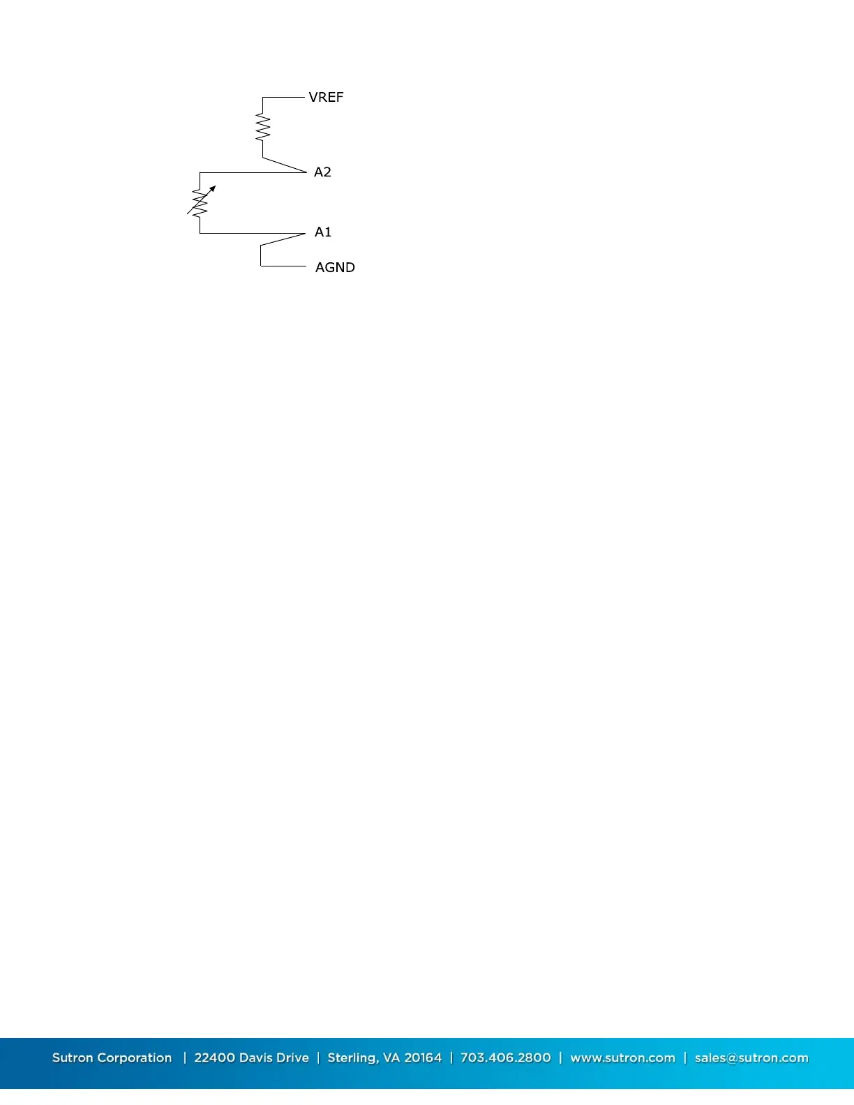
Figure 9 Resistance, Differential
The settings for resistance inputs are the same as voltage with the added setting of a reference
resistance. The reference resistor is connected as shown in the figure below. The resultant
resistance is only as accurate as the reference resistor. For the most accurate measurements,
use a resistor with low temperature sensitivity and high accuracy (e.g. VISHAY, S102C 10K000,
10K 0.01% resistor)
4-20mA
The 4-20mA input type simplifies the task of making the measurement of a 4-20mA sensor with
the output value having the units of mA prior to any processing. The settings for the 4-20mA
input type are the same as voltage, with the addition of a reference resistor. The resultant
measurement is only as accurate as the reference resistor. For the most accurate
measurements, use a resistor with low temperature sensitivity and high accuracy. For channels
1 & 2 the 8310 includes built in, temperature stable, highly accurate, 100 ohm resistors that are
automatically switched in during the measurement. Note, that most 4-20mA sensors require a
second or more to warmup so be sure to set the settling time (or warmup) to the value
recommended by the manufacturer. If the sensor needs to be continuously powered, then
change the appropriate jumper (AN1 or AN2) on the termination board to place the analog input
into current “I” mode which leaves the 100 ohm resistor always connected between the input
and ground. See Figure 14 - J9 - AN1 and AN2 input mode jumpers in the 8310-N
Protection/Termination Module Jumpers section for further details.
The overall range for the measurement is 0 to 22ma. However, any value < 3.8 or >21 will be
marked as BAD.
When using channels 1 and 2, the system uses an internal load resistor and switches it on/off
allowing you to wire to PROT+12 rather than SW12.
 Loading...