Do you have a question about the Suzuki Towbar Wiring Kit 13P and is the answer not in the manual?
Indicates a potential hazard that could result in death or serious injury.
Indicates a potential hazard that could result in minor or moderate injury.
Indicates a potential hazard that could result in vehicle or equipment damage.
Provides special information to make maintenance easier or instructions clearer.
Park vehicle safely, apply parking brake, and remove ignition key before installation.
Ensure no vehicle parts are damaged during the installation process.
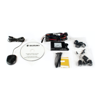
Check that all parts listed in the 'CONTENTS' section are present in the kit.
Avoid touching hot engine parts. Safely disconnect and secure the negative battery cable.
Refer to the Suzuki Service Manual for detailed installation information.
Apply specified torque when installing components for secure fitting.
Steps for removing rear bumper and related exterior parts for access.
Illustrates accessing interior panels for both Left Hand Drive and Right Hand Drive vehicles.
Diagrams showing specific vehicle points for bracket attachment and required measurements.
Procedure for drilling holes and securely mounting the main towbar bracket with specified torque.
Details harness length and optimal routing path through the vehicle.
Connecting the trailer socket and confirming a secure 'CLICK' connection.
Installing fasteners and performing checks to ensure connections are secure.
Illustrates the process of crimping wires for a reliable electrical connection.
Cleaning vehicle surfaces with solution and cloth for optimal adhesion.
Cutting and applying adhesive pads to secure components to the vehicle.
Cleaning specific areas on the vehicle body for final component attachment.
Cutting and applying protective strips to prevent damage to vehicle surfaces.
Instructions for cleaning the control module prior to mounting.
Securing the control module in its designated location within the vehicle.
Placing the control module into its final, secure position in the vehicle.
Connecting the main wiring harnesses to the control module, ensuring proper fit.
Detailed steps for routing and connecting various wiring harnesses to vehicle points.
Illustrates harness routing, specifically for vehicles without the blind spot system.
Securing the wiring harness in the trunk area, noting options for blind spot systems.
Final connections of harnesses and checks for secure and correct installation.
Routing the wiring harness along the vehicle's side and body panels.
Securing the harness with clips and performing visual checks for proper fitment.
Routing the remaining sections of the wiring harness to their final locations.
Final checks to ensure all harness connections are properly secured and made.
Procedure to access the fuse box located in the dashboard for LHD vehicles.
Procedure to access the fuse box located in the dashboard for RHD vehicles.
Connecting the wiring harness to the appropriate fuse box terminals.
Securing the fuse tap and performing checks for a correct electrical connection.
Routing the wiring harness discreetly through the vehicle's interior cabin.
Connecting the wiring harness to the rear section of the vehicle's body.
Re-installing rear covers and performing final checks on the installation.
Preparation and placement of interior components for both LHD and RHD vehicle types.
Procedure for opening and accessing the glove box compartment.
Mounting the electronic module securely inside the glove box.
Verifying the operation of trailer lights (stop, turn, reverse) after connection.
Overview of optional kits for connecting different types of trailer wiring.
Testing specific trailer light indicators and signals for proper function.
Information on choosing and using different trailer plug adapters.
Illustrates the correct procedure for connecting the trailer plug.
| Brand | Suzuki |
|---|---|
| Model | Towbar Wiring Kit 13P |
| Category | Automobile Accessories |
| Language | English |