SUZUKI GENUINE ACCESSORIES
English_I-M 990E0-54P56-010 Rev00 03/09/2018
1
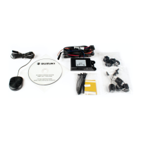
Description:
Front parking system
Part number:
990E0-54P56-010
Applications:
VITARA (LY) TSMLY…600001 - … LHD/RHD
Fitting time:
1h
Beschreibung:
ParkAssistent vorn
Teile Nr:
990E0-54P56-010
Verwendung:
VITARA (LY) TSMLY…600001 - … LHD/RHD
Montagezeit:
1h
Désignation:
Système d'aide au stationnement avant
N° de code:
990E0-54P56-010
Utilisations:
VITARA (LY) TSMLY…600001 - … LHD/RHD
Temps
de montage:
1h
Descrizione:
Sensori di parcheggio anteriori
Numero di codice:
990E0-54P56-010
Applicazioni:
VITARA (LY) TSMLY…600001 - … LHD/RHD
Tempo
d’installazione:
1h
Descripción:
Sensores de aparcamiento delanteros
Código:
990E0-54P56-010
Aplicación:
VITARA (LY) TSMLY…600001 - … LHD/RHD
Tiempo de
instalación:
1h
INSTALLER AND USER INSTRUCTIONS
MANUALE DI INSTALLAZIONE ED USO
INSTALLATIONS-UND BEDIENUNGSANLEITUNG
MANUAL PARA INSTALADOR Y USUARIO
MANUEL INSTALLATEUR ET UTILISATEUR
GB
ΕΓΧΕΙΡΙ∆ΙΟ ΕΓΚΑΤΑΣΤΑΣΗΣ ΚΑΙ ΧΡΗΣΗΣ
FR
DE
IT
ES
TELEPÍTÉSI ÉS KEZELÉSI UTASÍTÁSOK
INSTRUKCJA MONTAŻU I OBSŁUGI
INSTALLERINGS- OG BRUGERVEJLEDNING
INSTRUCTIES VOOR DE INSTALLATEUR EN DE GEBRUIKER
ИНСТРУКЦИЯ ПО УСТАНОВКЕ И ЭКСПЛУАТАЦИИ
INSTALLASJONS- OG BRUKERVEILEDNING
NÁVOD NA INSTALACI A POUŽITÍ
ASENTAJAN JA KÄYTTÄJÄN OHJEET
ІНСТРУКЦІЯ З МОНТАЖУ ТА ЕКСПЛУАТАЦІЇ
NÁVOD NA INŠTALÁCIU A POUŽITIE
INSTALLATIONS- OCH ANVÄNDARINSTRUKTIONER
INSTRUCŢIUNI DE INSTALARE ŞI UTILIZARE
KORISNIČKI PRIRUČNIK S UPUTAMA ZA POSTAVLJANJE
KURUCU VE KULLANICI TALİMATLARI
NAVODILA ZA MONTAŽO IN UPORABO
INSTRUÇÕES PARA O INSTALADOR E UTILIZADOR