Do you have a question about the Swegon BlueBox Tau SKY Hi HP and is the answer not in the manual?
| Brand | Swegon |
|---|---|
| Model | BlueBox Tau SKY Hi HP |
| Category | Air Handlers |
| Language | English |
Details on product conformity with regulations and directives.
Information on symbols and labels used in the manual and on the unit.
Key safety principles and responsibilities for unit operation and access.
Guidelines for safe unit operation, including protective measures and forbidden actions.
Information on unit noise levels and remaining hazards not eliminated by design.
Safety information on refrigerant R32, hazards, and health consequences of accidental release.
Procedure for checking the unit upon delivery for damage.
Guidelines for safely moving and handling the unit, including lifting precautions.
Recommendations for storing the unit indoors or outdoors, considering ambient conditions.
Overview of documentation and classification of units regarding Ecodesign Directive.
Allowed applications and required conformity based on operating conditions.
Defines the correct use of the unit and prohibited applications.
Description of the microprocessor control and integrated safety devices for unit management.
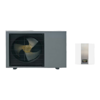
Explanation of the unit's operating cycle and its physical construction.
Technical specifications of the air-condensed water chiller unit.
Instructions for operating the unit via the V5+ base controller: ON/OFF, mode, setpoint.
Instructions for operating the unit via the V6 advanced controller: ON/OFF, mode, setpoint.
Information on wiring diagrams and supplied cables for unit installation and connection.
Considerations for choosing the installation location and required unit dimensions.
Guidelines for positioning the external unit, including height and anchoring.
Procedure for assembling the optional base frame for unit installation.
Instructions for installing the internal unit, including wall mounting.
Details on using anti-vibration mounts, noise reduction, and minimum spacing requirements.
Examples of possible system configurations and their compatibility with controllers.
Steps and components for correctly connecting the unit's hydraulic circuit.
Guidelines for safely making electrical connections, including grounding and protection.
Information on the unit's refrigerant charge and procedures for vacuum and filling.
Steps for configuring the WiFi module for remote monitoring and control.
Essential checks and preparatory steps before starting the unit for the first time.
Procedures for initial unit start-up and testing the hydraulic circuits.
Verification of unit components and operations after initial start-up.
Checking and calibrating safety components like pressure switches.
Monitoring key parameters during stable unit operation.
Identifying and resolving common unit alarms and malfunctions.
Instructions for temporary and long-term stopping of the unit.
Information on adjusting operational parameters via the control interface.
Guidelines for cleaning the finned pack heat exchanger and plate heat exchangers.
Instructions for cleaning the electrical control panel and compressor compartment.
Schedule and procedures for routine checks to ensure correct unit operation.
Procedures for prompt handling of special situations and work.
Visual representations of hydraulic components and functions used in diagrams.
Icons and buttons used on the base controller (V5+) and advanced controller (V6) interfaces.
List and definitions of acronyms and abbreviations found in the manual.
Identification of components in exploded views for internal and external units.
Overview of supplementary documents and diagrams available in the appendices.