7
Fontan Mobilstar E and ER
Device start
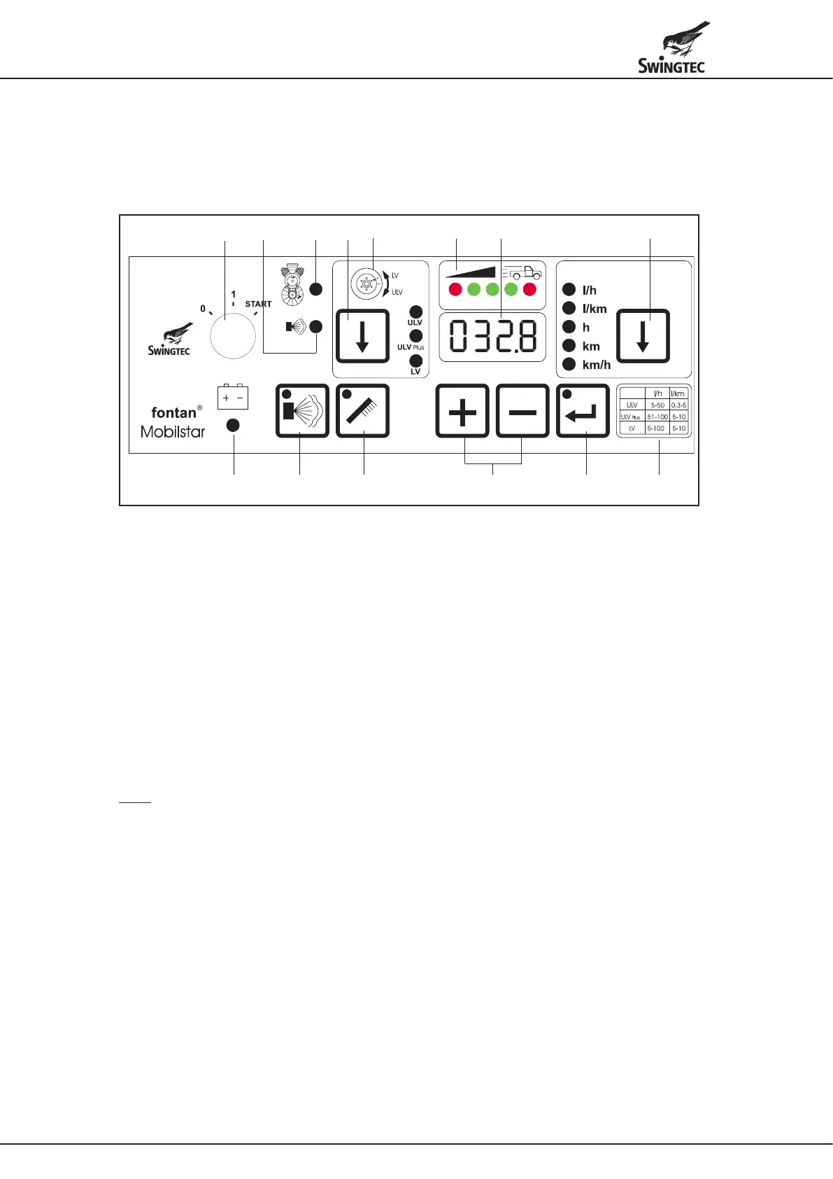
Control unit / remote control
The control unit is attached to the device and can be detached and used as a remote control (e.g. in the driver's cab).
a m b dn
k fhgji
l
c
e
a Ignition key
b ULV / ULV-Plus / LV spraying method selector button
The spraying method is indicated by LEDs.
c Note on correct setting of the spray heads
ULV / ULV-Plus or LV (see page 4 below)
d Display
e * Output method litres per hour or litres per kilometre button
The selected method is indicated by LEDs.
The operating hours (h), the distance travelled (km) and the current vehicle speed (km/h) can also be called
up with the button. The vehicle speed is shown in display “d”.
f Table of output capacities “litres/hour” and “litres/km” for ULV / ULV-Plus / LV spraying methods
g Input buttons for spray output (shown in display “d”)
h ConrmationbuttonfortheselectedsprayingprogramwithLED
i Spray button with LED
j Rinse button with LED
k LED display: device ready
l LED display: malfunction in fog liquid system
m LED display: malfunction in motor/compressor system
n * Display of the correct vehicle speed (green and red LEDs)
* Note
The displays and functions l/km and km, km/h and the correct vehicle speed “n” listed under “e” apply only to the
Mobilstar ER device.
All other indicators and functions apply to both the Fontan Mobilstar E and ER devices.
• Preparation according to the regulations on page 4.
• The Fontan Mobilstar E and ER models are not equipped with a spraying tank. The fog liquid is conveyed through
a stainless steel pump from a separate tank. We offer spraying tanks with capacities of 69 l (stainless steel), as well
as 80 l, 150 l, 300 l and 500 l (polyethylene). All tanks are equipped with a quick coupling for connecting the solution
line (16) and with a ventilation in the tank cap.
• Connect the solution line page 5 (d) to the quick coupling on page 5 (e).
• The emergency shutdown page 4 (5) must be unlocked.
• Set the ignition key (a) to the “1” position.
• Select the ULV or ULV-Plus or LV spraying methods with button (b).
• Select the output method (l/h) with button (e) (indicated by LED).
• Enter the spray output (l/h) with buttons (g) according to the values given in table (f). The selected spray output is
shown on the display (d).
• Press the confirm button (h) for the selected spraying program.
• Start the engine by turning the ignition key to the right or by pressing the start button (7). The ignition key must be in
the “1” position.
When starting the device, the choke (13) must be pulled. The choke can be accessed through an opening in the
hood of the device and must be pushed back immediately after the device starts.


 To Next Page
 Loading...