3
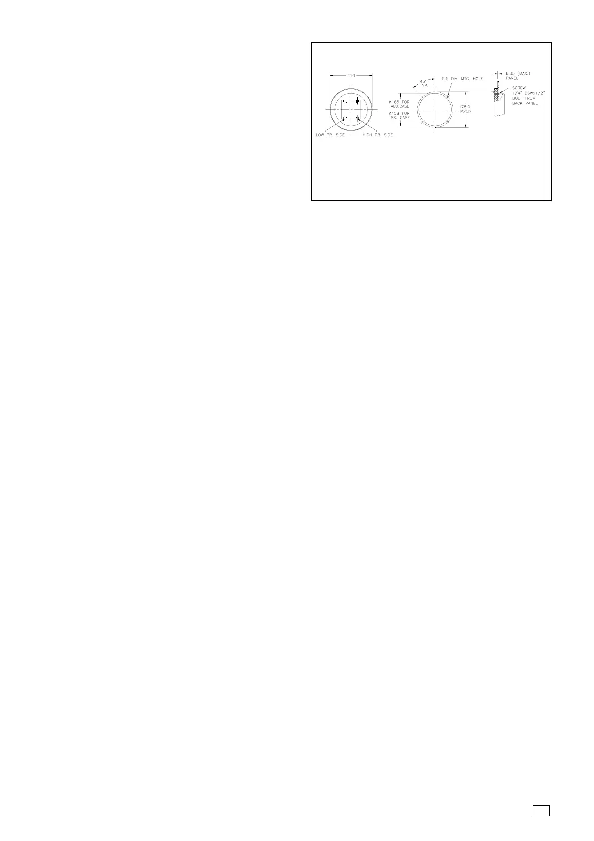
FLUSH OR PANEL MOUNTING
Remove the gauge cover and provide a hole in the
panel as per the mounting dimensions. Mount the
gauge with the foue M5 mounting studs & nuts. Orient
the axes of the dial for readability and appearance and
wrench tighten the retaining nuts. Replace the gauge
cover. Torque screws evenly to avoid overstressing lens
window on the gauge.
WALL MOUNTING
Drill four mounting holes on wall to match the 71.5 mm
pitched mounting holes of the bracket. Secure
instrument with bolts and nuts.
PIPE MOUNTING
Mount the instrument onto a 2" Pipe using the pair of “ U ” bolts & nuts and secure the instrument & orient the gauge
as required and tighten the bolts firmly. Ensure rigidity.
CAUTION : Do not orient by turning or grasping the indicator case.
H CERTAIN PRACTICES SHOULD BE FOLLOWED ON ALL FLOW AND LIQUID LEVEL D.P GAUGE PIPING
" Make up all joints using a suitable pipe joint compound to reduce measurement errors caused by leaks in the pipe
joints.
" Slope all piping at least 1 inch per linear foot to avoid liquid or gas entrapment.
" If process media exceeding 200° F (93°C ) is to be measured, provide 2 feet of un-insulated piping between the
primary device and the D.P Gauge for each 100° F (37.8°C ) in excess of 200° F.
" Install a valve manifold connecting the D.P Gauge and the differential pressure source to facilitate operation and
checking of the D.P Gauge. Locate shutoff and bypass valves to be readily accessible to the operator from the
front of the instrument.. The shutoff valve should be the first valve from the process line or vessel.
" D.P Gauge have two pairs of 1/4" NPT pressure connections.
I INSTRUMENT START UP
IMPORTANT : Prior to placing the instrument in service, perform the following operations
# Since the bellows may have taken a slight “set” due to possible extended periods of storage prior to installation,
it is advised that the first time the D.P Gauge is used and prior to actual operation, the unit be exercised to ensure
correct indications. To exercise the unit, sequentially apply maximum and minimum differential pressure to the
high pressure side for at least ten cycles.
# Open up the Front Bezel and the Dial Lens and remove the sponge placed beneath the pointer. Pressurisation
without removal will lead to Pointer shift from its original position.
# Although the D.P.Gauge is a seamless Rupture-proof bellows type instrument, care should be taken not to
subject the instrument to unnecessary shock or over range pressure during startup .Connect a Three valve manifold
Block . Make sure block and bypass valves are closed when beginning start-up procedures.
# Check manifold and piping for leakage by opening the block valves, one shutoff valve and the bypass valve to
pressurize the instrument. Then close the shutoff valve and by pass valve to pressurize the instrument. If pointer
travels upscale, then it indicates leak in low pressure piping; & if pointer travels downscale, then it indicates leak
in high pressure piping.
# Zero check the instrument. To do this, close the block valves and open the bypass valve. This equalises the
pressure on both sides of the instrument. If the instrument does not indicate zero, set pointer to zero by rotating
Dial by loosening the zero Adjust Screw on the Dial & re-tighten it after Zero adjustment.
# TO CHECK CALIBRATION
First zero the instrument at atmospheric pressure & connect a calibration instrument such as Swiscal Digital
Portable Manometer to the high pressure connection of the Gauge. The low pressure connection is vented to
atmosphere. With the help of an aspirator bulb or regulated air source apply increasing pressures of 20, 50, 80 and
FLUSH PANEL MOUNTING
BACK VIEW PANEL CUTOUT MOUNTING DETAIL
 Loading...