4
100 percent, of full-scale differential to the HP housing. Exercise care to always approach the desired scale
reading from the low D/P side; if you overshoot and drop back to the reading, your calibration will be incorrect.
Repeat the procedure, by reducing pressure and stopping at the same scale readings, now taking care to always
approach readings from the high D/P side. Compare D.P Gauge readings with the Master Gauge.
Inconsistent readings may be the result of the pointer dragging against the scale plate. To inspect for this
condition, remove the lens. The end of the pointer should be no closer to the scale plate than 1/32 inch throughout
its arc of travel. If necessary, bend the pointer away from the scale by gently pulling on the outer end.
If indications are within specified tolerances, no further calibration is required.
If instrument readings are outside specified tolerances, re-calibration is required. Send the instrument to factory.
# To Set the Switch Actuation
The Switch setting are to be done after opening up the bezel. With a screw driver adjust the positioning of the set
pointer in the arrow direction marked up on the dial. Before commissioning check up the functioning of the
switching action during the calibration check explained above.
After instrument has been checked to read correctly, replace lid and/or glass assembly.
J INSTRUMENT INSTALLATION RECOMMENDATIONS
♦ Rapid pressurization can cause severe damage, to the sensing element, in all types of pressure instruments.
Modest quality instruments (± 2 to 5% full scale accuracy) are usually unaffected by this type abuse because of
their relatively simple design. More sophisticated instruments (± 1 % full scale accuracy, or better) are quite
likely to be damaged by rapid pressurization or over range.
♦ Most better quality instruments have an over range protection mechanism built into them, but since they are
mechanical in design, they cannot be relied on to react in time to protect the instrument against such a rapid
change in pressure. (This is one reason rupture disks, in addition to pressure relief valves, are required on some
pressure vessels.
♦ As explained earlier the simplest method of avoiding this problem (for differential pressure instruments) is by
installation, and proper use of, a three valve manifold . Opening the equaliser valve, prior to opening one or both
of the block valves, will tend to insure that pressure is applied simultaneously to both sides of the sensing
element.In addittion to this arrangement the snubbers supplied along with the instrument offers a back up protection.
♦ As a general practice wherever possible, instruments should be located at a higher elevation than the process connections
on the equipment, or process device, on which they are being installed. Frequently, when trouble is encountered, it is
found that the instrument has been installed at an elevation below the process connections, allowing particulate matter
to flow by gravity into the instruments, resulting in erratic performance or complete malfunction. If for viewing
properties, or other reasons, the above recommended location is impractical, there is an alternative procedure. Provide
either a “pigtail” loop, or a “dropleg” (U–tube manometer configuration) in the tubing between the instrument and the
process connections. Since most instruments do not have flow through them, such an installation practice will insure
that solids will not be moved, by gravitational force, into the instrument.
However a more detailed line up procedures for typical & special installations are presented in Figures 2
through 14.
Use the diagram most applicable for specific requirement as a guide.
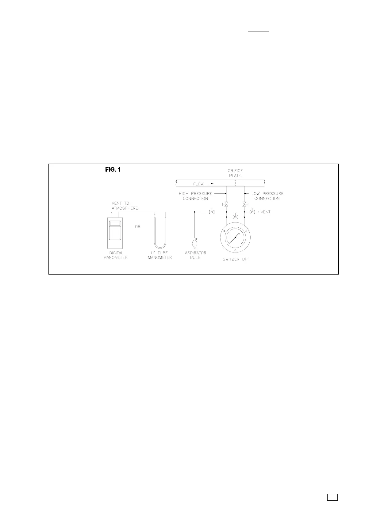
TYPICAL SCHEMATIC ARRANGEMENT FOR CALIBRATION OF D.P. GAUGES
 Loading...