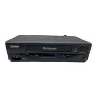
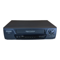
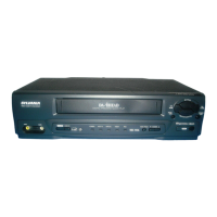
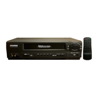
This document serves as a service manual for the Emerson and Sylvania branded Video Cassette Recorders, specifically models EWV601A, KVS600A, and SSV6001A. It provides comprehensive information for servicing, maintenance, and repair of these devices.
The manual is structured into three main sections:
- Main Section: Covers general specifications, preparation for servicing, adjustment procedures, schematic diagrams, and circuit board assemblies (CBAs).
- Deck Mechanism Section: Focuses on standard maintenance, alignment, disassembly/assembly, and alignment procedures for the deck mechanism.
- Exploded Views and Parts List Section: Contains detailed exploded views and lists of mechanical and electrical parts.
Function Description:
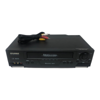
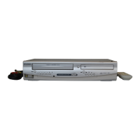
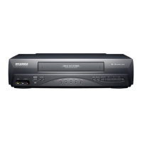
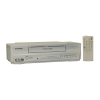
The devices are Video Cassette Recorders (VCRs) designed for recording and playback of video cassette tapes. They feature standard VCR functionalities, including play, record, fast forward, rewind, pause/still, and eject. The units also incorporate a tuner for receiving broadcast signals, allowing for direct recording from television. Specific models may include additional features such as Hi-Fi audio capabilities, which offer enhanced sound quality. The front panel includes a cassette compartment, various control buttons (REW, STOP/EJECT, PLAY, F.FWD, PAUSE/STILL, MENU, REC/OTR, CHANNEL, TAPE SPEED, VCR/TV, POWER), and a display window showing indicators for power, VCR/TV mode, tape presence, timer, and recording status. The rear panel provides connectivity options such as AC power input, audio/video input and output jacks, antenna input, and antenna output with a CH3/CH4 selector switch. Remote control functionality is also supported, offering a wider range of control buttons including number buttons, display, slow motion, counter/memory, and exit/reset.
Important Technical Specifications:
The specifications are categorized into Video, Servo, Normal Audio, Tuner, and Hi-Fi Audio.
Video:
- Video Output (PB): 0.8 Vp-p (minimum), 1.0 Vp-p (nominal), 1.2 Vp-p (maximum) in SP Mode.
- Video Output (R/P): 0.8 Vp-p (minimum), 1.0 Vp-p (nominal), 1.2 Vp-p (maximum) in SP Mode.
- Video S/N Y (R/P): 40 dB (minimum), 45 dB (nominal) in SP Mode, without burst.
- Video Color S/N AM (R/P): 37 dB (minimum), 41 dB (nominal) in SP Mode.
- Video Color S/N PM (R/P): 30 dB (minimum), 36 dB (nominal) in SP Mode.
- Resolution (PB): 230 Lines (minimum), 245 Lines (nominal) in SP Mode.
Servo:
- Jitter Low: 0.07 µsec (nominal), 0.12 µsec (maximum) in SP Mode.
- Wow & Flutter: 0.3 % (nominal), 0.5 % (maximum) in SP Mode.
Normal Audio:
- Output (PB): -9 dBV (minimum), -6 dBV (nominal), -3 dBV (maximum) in SP Mode.
- Output (R/P): -9 dBV (minimum), -6 dBV (nominal), -1.5 dBV (maximum) in SP Mode.
- S/N (R/P): 36 dB (minimum), 41 dB (nominal) in SP Mode.
- Distortion (R/P): 1.0 % (nominal), 4.0 % (maximum) in SP Mode.
- Freq. resp (R/P) at 200Hz: -11 dB (minimum), -4 dB (nominal) in SP Mode.
- Freq. resp (R/P) at 8kHz (-20dB ref. 1kHz): -14 dB (minimum), -4 dB (nominal) in SP Mode.
Tuner:
- Video output: 0.8 Vp-p (minimum), 1.0 Vp-p (nominal), 1.2 Vp-p (maximum) in E-E Mode.
- Video S/N: 39 dB (minimum), 42 dB (nominal) in E-E Mode.
- Audio output: -10 dB (minimum), -6 dB (nominal), -2 dB (maximum) in E-E Mode.
- Audio S/N: 40 dB (minimum), 46 dB (nominal) in E-E Mode.
Hi-Fi Audio:
- Output: -12 dBV (minimum), -8 dBV (nominal), -4 dBV (maximum) in SP Mode.
- Dynamic Range: 70 dB (minimum), 85 dB (nominal) in SP Mode.
- Freq. resp (6dB B.W): 20 ~ 20K Hz in SP Mode.
Usage Features:
The VCRs are designed for straightforward operation with a clear front panel display and a comprehensive remote control. The display panel uses LED indicators to show the current operational status:
- POWER: "H" (Light on) for power on, "L" (Light off) for power off.
- VCR/TV: "H" for VCR mode, "L" for TV mode.
- TAPE IN: "H" for cassette in, "L" for cassette out.
- TIMER: "H" for Timer stand by, One touch recording, or Timer recording; "L" for General mode.
- REC: "H" for REC mode, "L" for REC pause or General mode.
Error conditions are indicated by blinking LEDs:
- TAPE IN blinking at 0.8Hz: Reel and capstan mechanism not functioning correctly.
- TAPE IN blinking at 1.6Hz: Tape loading mechanism not functioning correctly.
- TAPE IN blinking at 3.2Hz: Cassette loading mechanism not functioning correctly.
- TAPE IN blinking at 6.4Hz: Drum not working properly.
- REC blinking at 0.8Hz: REC pause.
Maintenance Features:
The service manual provides detailed instructions for maintaining the VCRs, emphasizing safety and proper procedures.
- Important Safety Precautions: Highlights critical safety-related parts (marked with a triangle symbol) and procedures to prevent shock, fire, or other hazards. It includes guidelines for replacing components, handling internal wiring, and connecting/disconnecting internal connectors.
- Safety Check after Servicing: Outlines checks for clearance distance and leakage current to ensure compliance with safety standards after repairs.
- Standard Notes for Servicing: Provides guidance on circuit board indications and instructions for handling connectors, especially Flexible Foil Connectors (FFC). It also details methods for removing and installing Flat Pack-ICs using hot-air desoldering machines or soldering irons, with cautions against damaging surrounding components or circuit board foils.
- Preparation for Servicing: Describes how to enter the service mode, including instructions for activating/deactivating optical sensors and using the REC-Safety Switch for recording during servicing.
- Standard Maintenance Schedule: Recommends periodic checks and changes for various deck components, including the cylinder assembly, loading motor, pulley assembly, tension lever, AC head assembly, reels, capstan motor, cap belt, FE head, idler assembly, pinch arm assembly, and brake assemblies. Cleaning of tape transport parts (upper drum with video head, pinch roller, audio control head, full erase head) with 90% Isopropyl Alcohol is emphasized.
- Cleaning Procedures: Specific instructions for cleaning the video head (using a head cleaning stick or chamois cloth with 90% Isopropyl Alcohol, avoiding vertical cleaning) and the audio control head (using a cotton swab with 90% Isopropyl Alcohol).
- Service Fixture and Tools: Lists specialized tools required for alignment, such as alignment tapes (FL8A, FL8N, FL8NW), guide roller adjustment screwdrivers, mirrors for tape transportation checks, azimuth adjustment screwdrivers, and X-value adjustment screwdrivers.
- Mechanical Alignment Procedures: Detailed steps for manual tape loading/unloading, placing the cassette holder in the tape-loaded position without a cassette, and tape interchangeability alignment (adjusting guide rollers, X-value, envelope waveform, and azimuth of audio/control/erase head).
- Disassembly/Assembly Procedures of Deck Mechanism: Step-by-step instructions for disassembling and reassembling various deck components, ensuring proper alignment and lubrication.
- Electrical Adjustment Instructions: Procedures for adjusting the head switching position to prevent noise and vertical jitter in the picture, using an oscilloscope and alignment tape.
- Power Supply Trouble Shooting Guide: A flowchart and detailed repair methods for diagnosing and fixing power supply issues, including checks for fuses, rectifying diodes, switching FETs, control transistors, and feedback circuits.
- Schematic Diagrams / CBA's and Test Points: Provides circuit diagrams with component identification, voltage indications, and test points for troubleshooting.
- Waveforms: Illustrates expected waveforms at various test points for diagnostic purposes.
- IC Pin Function Descriptions: Lists the functions and active levels of pins for key integrated circuits, such as the servo/system control IC.
- Lead Identifications: Diagrams for identifying the leads of various transistors and other components.