2
PARTS LIST
Mounting bracket ..............................................................................................................1
Screws ................................................................................................................................. 4
Wall Anchor ........................................................................................................................ 4
INSTALLATION
Tools required:
• Electricdrill
• Phillips(cross-head)screwdriver
• Tapemeasure
Choose a suitable location for mounting the convector:
A. The location shall have enough space and clearance as illustrated in Fig. 1.
B. The power outlet shall be accessible by the electrical cord of this convector
without using an extension cord.
C. The power outlet shall not be located directly behind or above the convector.
WALL MOUNTING INSTRUCTIONS
1. Release the mounting bracket by pressing the locking brackets on both sides.
2. Use the mounting bracket as a template by holding it against the wall as
illustrated in Fig. 1.
3. Follow the dimensions specified in Fig 1 and place mounting bracket in the
desired location.
4. Markthe4screwholes.Placemountingbracketonthescrewmarkingsand
ensure the mounting bracket is perfectly level.
5. Predrillholesandinsert4wallanchors.Wallanchorsareneededfor
mountingondrywallorconcretewalls.Ensureyouusetheproperanchors
for your wall type.
6. Replacethemountingbracketandfastenitwithscrews(minimum4screws).
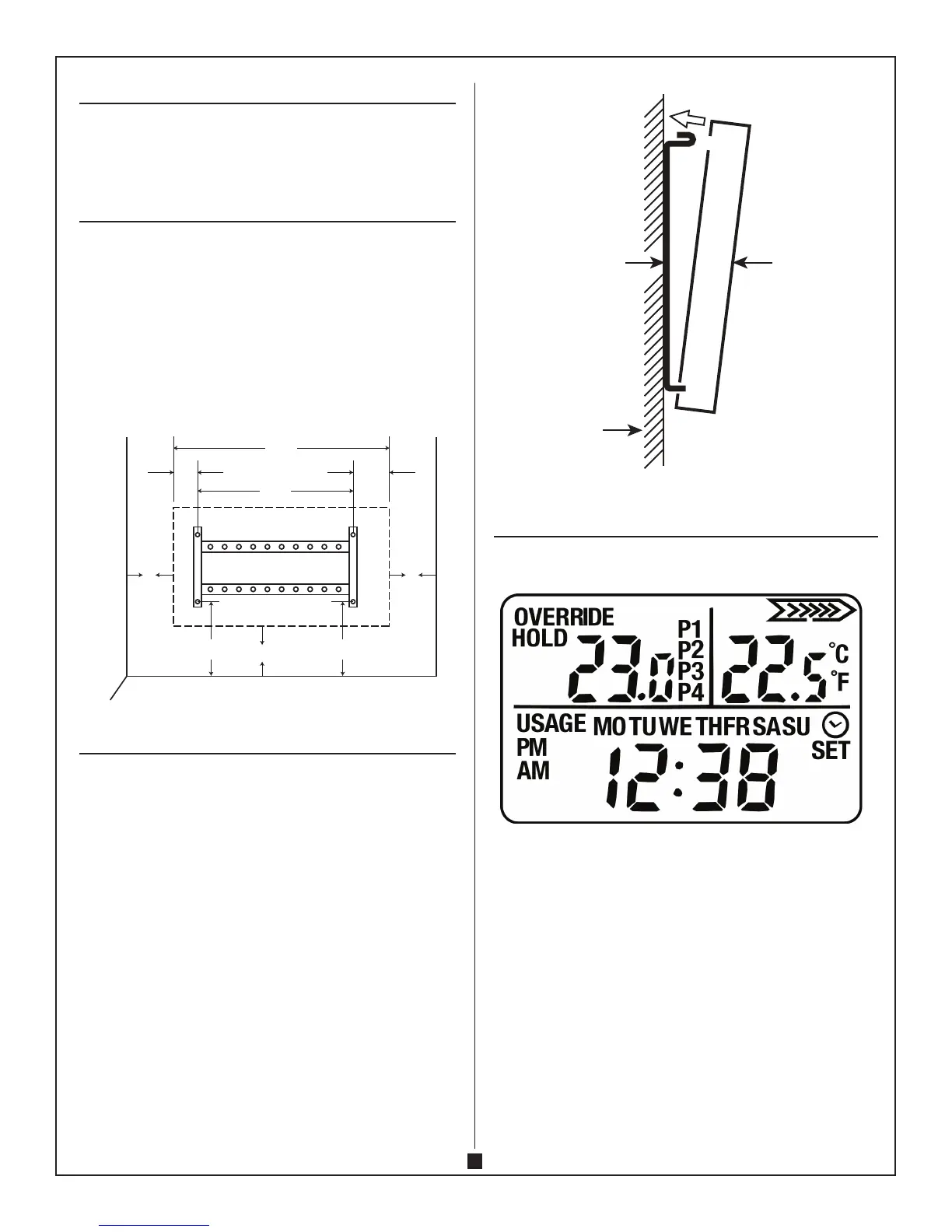
7. Mount the convector to the mounting bracket and engage the 2 locking
brackets at the top. See Fig. 2.
CAUTION – HIGH TEMPERATURE, RISK OF FIRE. KEEP ELECTRICAL
CORDS, DRAPERY, FURNISHINGS AND OTHER COMBUSTIBLES AT LEAST
3 FT (0.9 M) AWAY FROM THE FRONT OF THE HEATER AND AWAY FROM
THE SIDE AND OF HEATER.
WARNING – TO REDUCE RISK OF FIRE, DO NOT STORE OR USE
GASOLINE OR OTHER FLAMMABLE VAPORS AND LIQUIDS IN THE
VICINITY OF THE HEATER.
Fig. 2
Wall
Wall bracket Convector
OPERATION
Turn the “0/I” switch on the right side of the convector to “I” position. The indicator
light and display will be ON.
1. Time setting–PressMODEbuttonandpressUPandDOWNbuttonsatthe
same time.
A. PresstheUPorDOWNbuttontosetthe‘DAY’fromMONDAY(MO)–
TUESDAY(TU)–WEDNESDAY(WE)–THURSDAY(TH)–FRIDAY(FR)–
SATURDAY(SA)–SUNDAY(SU).
B. PressMODEbuttonagain.Thedisplay‘HOUR’willashandthenpress
theUPorDOWNbuttontosetthe‘HOUR’.
C. PressMODEbuttonagain.Thedisplay‘MINUTE’willashandthenpress
theUPorDOWNbuttonagaintosetthe‘MINUTE’.
D. PressMODEbuttonagaintoexitandsavethesetting.
Fig. 1
WIDTH OF CONVECTOR
15.3 cm
(6 in)
15.3 cm
(6 in)
Minimum
clearance to
adjacent
surface
15.3 cm
(6 in)
Minimum
clearance to
adjacent
surface
Minimum
distance
to ground
58.1 cm
(22.9 in)
33.7 cm
(13.3 in)
9.8 cm
(3.9 in)
14.6 cm
(5.75 in)
22.2 cm
(8.75 in)
22.2 cm
(8.75 in)
 Loading...