Do you have a question about the SymCom MOTORSAVER 455-480R and is the answer not in the manual?
Essential safety warnings and requirements for installation personnel.
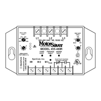
Details on connecting line and load side terminals, including special cases for 2-pole contactors.
Instructions for connecting the output relay to control the motor starter coil.
Adjusting the voltage setting to match the nominal 3-phase line voltage for motor protection.
Setting the delay before output contacts close after acceptable power is restored.
Configuring the trip level for voltage unbalance based on NEMA standards.
Setting the time delay before tripping on voltage faults, excluding single-phasing.
Procedure for powering up the unit and indicators to observe.
Common symptoms and their corresponding solutions for operational issues.
Explanation of LED indicator status and their meaning.
Detailed electrical ratings, trip/reset points, and delay times.
Information on passed standards, power consumption, weight, and operating temperature.
Details on product warranty periods and terms.