422
13
Remote Bypass WiringAppendix A
For those installations that may require remote bypassing of the 422's functions, a rear panel jack
has been provided to accept an external switch for this purpose. The external switch should be a
high quality, industrial grade, single pole, double throw toggle switch. We highly recommend that
shielded wire be used to connect the switch to the 422 so as to minimize the possibility of introduc-
ing any radio frequency interference into the 422. The external 1/4" audio plug should be of the
tip-sleeve type (often referred to as a mono plug). The following diagram illustrates recom-
mended wiring practice.
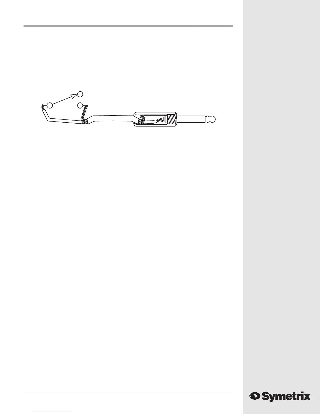
The cable should be wired as shown above and as described below:
1. The tip of the 1/4" plug is soldered to one end of the signal wire of a coaxial cable.
2. One end of the shield of the coaxial cable is soldered to the sleeve of the 1/4" plug.
3. The other end of the signal wire is soldered to the common terminal of a single pole, double
throw switch.
4. The remaining shield is soldered to either of the remaining terminals of the switch (one
terminal remains unconnected).
User supplied remote bypass circuitry
Bypass
In (operate)