13/26
User’s Guide
6200 Digital
Voice Processor
To download the latest version of 6200 Designer, a Windows GUI
application interface for the 6200, go to: www.airtoolsaudio.com
Bypass
The 6200 has two bypass modes - software (DSP) and hardware (relay). The DSP (SW) bypass can be invoked a number of
ways. The hardware (HW) bypass is only accessible via contact closure wired to a rear panel euroblock connector.
DSP (SW) BYPASS:
DSP (SW) Bypass mode can be invoked by several means:
1. Pressing the BYPASS button on the front of the 6200 while in one of the top-level menus (Home, In LVL or Out LVL).
2. Pressing the BYPASS (PROGRAM 0) button on an attached RC-1 remote.
3. Pressing the DSP Bypass button in an attached (and currently “online”) 6200 Designer GUI.
4. Activating a contact closure attached to the SW and Ground terminals of the rear panel REMOTE BYPASS connector.
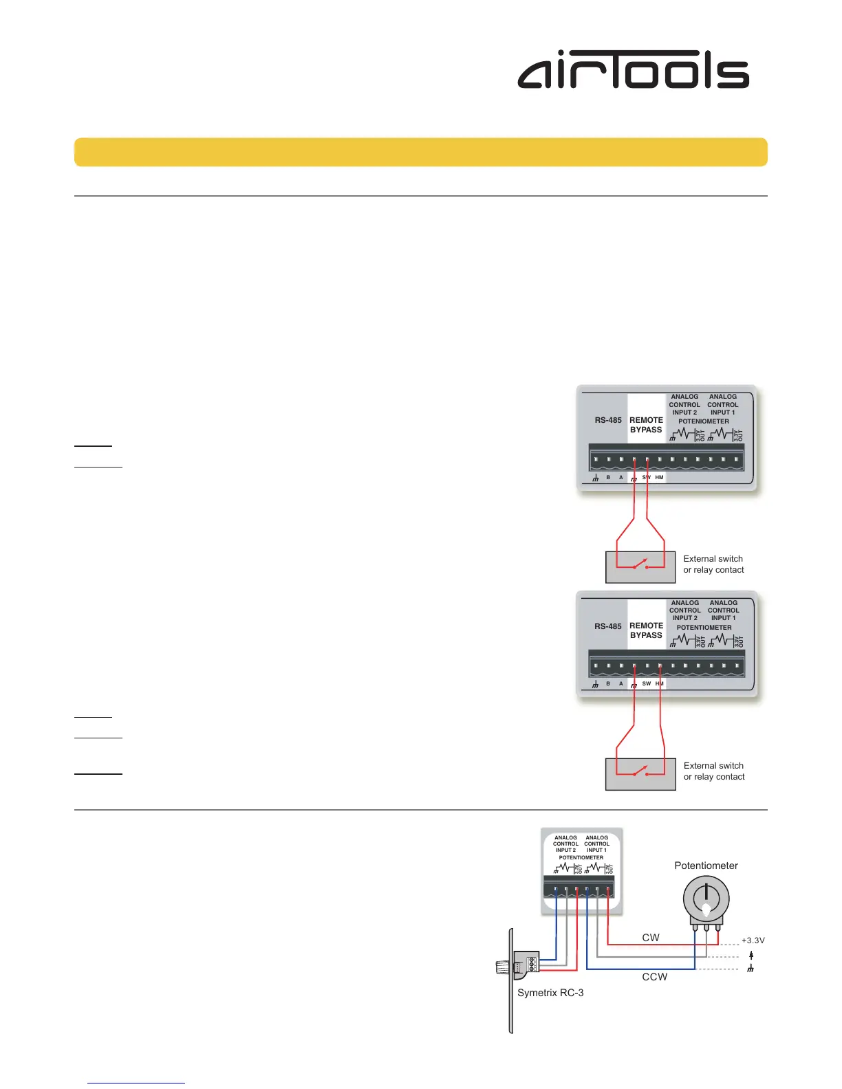
DSP (SW) Bypass switch wiring:
The figure right shows the connection of a contact closure to the SW Bypass function of
the REMOTE BYPASS connector.
NOTE: A latching switch should be used in order to hold the bypass state.
NOTE 2: The switch on the REMOTE BYPASS connector will both override and interrupt
the bypass state set by methods 1 through 3 listed above.
HARDWARE MUTE (HM):
Hardware Mute (HM) isn’t a true “bypass” or “mute” but actually a relay-activated output
disconnect. It is only accessible by activating a contact closure attached to the HM and
Ground terminals of the rear panel REMOTE BYPASS connector.
Hardware Mute (HM) switch wiring:
The figure right shows the connection of a contact closure to the Hardware Mute function
of the REMOTE BYPASS connector.
NOTE: A latching switch should be used in order to hold the bypass state.
NOTE 2: Activating the Hardware Mute function invokes relays which completely
disconnect all active circuitry from their associated output connections.
NOTE 3: Hardware Mute is automatically engaged upon loss of power.
Analog Control Inputs
The 6200 features two analog control inputs which provide real-time control of up to two parameters per port using standard
10k Ohm linear potentiometers. The figure right shows the connections.
Calibrating an Analog Control Input
Once you have wired up your pot to an analog control input, it should be
calibrated to ensure the full travel of the pot is read correctly by the 6200.
1. Press the HOME button to ensure we are starting from the top.
2. Press the NEXT button once.
3. The display should read “Section to Edit, - Channel 1 Menu -”.
4. Turn the ADJUST knob clockwise until the menu reads “Section to Edit,
- Setup Menu -”.
5. Press the NEXT button once.
6. Turn the ADJUST knob clockwise until the menu reads “- Setup Menu -,
-- External Controls --”.
Bypass, Analog Control Inputs
External switch
or relay contact
External switch
or relay contact
Potentiometer
CCW
CW
+3.3V
Symetrix RC-3
 Loading...