Master Language is English Hot Runner System Installation Guide SVC-17-0001_EN-Rev13
RESTRICTED: Property of Synventive. - 102 - All rights reserved. Errors and omissions excepted
For limited third party distribution based on need and intended use. © 2021 Synventive Molding Solutions
H O T R U N N E R T E C H N O L O G Y
Hot Runner System Installation Guide
Service and Maintenance / Actuator HB Series
8.1.1.11 Valve Pin Adjustment
Hot Surfaces Hazard
Contact between the skin and hot surfaces could result in
burns.
Use personal protective equipment, such as gloves, apron,
sleeves and face protection, to guard against burns. When
servicing or handling the hot runner system outside the manifold
plates or the injection molding machine, care must be taken to
heed the hot surface exposure warnings.
1) Bring the manifold and mold to the operating temperatures for the
material to be molded.
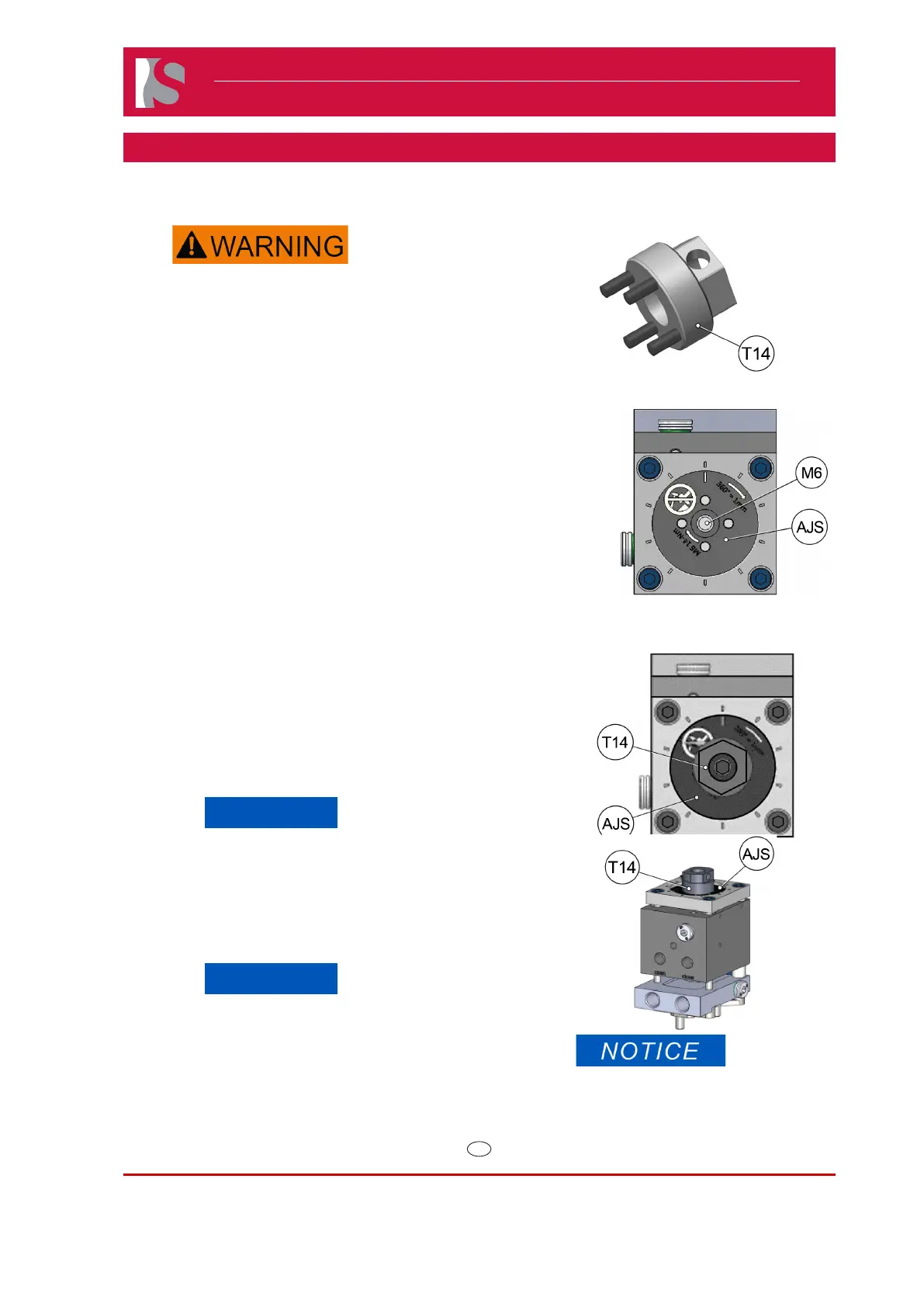
2) Insert the adjustment tool (T14), Synventive part number ATA01,
on the top of the actuator.
3) Loosen the locking screw (M6).
4) Close the valve gate by applying pneumatic pressure on the
closed port.
5) Rotate the adjusting screw (AJS) in a clockwise (forward)
direction to pre-set the valve pin position.
● Conical Gate: Turn the adjusting screw (AJS) clockwise
until the valve pin seats rmly in the gate.
When valve pin position is achieved, then turn adjusting
screw clockwise (forward) an additional 1/10th of a turn
in order to achieve proper valve pin position during
operation. 1/10th increments are provided adjacent to
the screw for reference.
● Cylindrical Gate: Turn the adjusting screw (AJS)
clockwise until the valve pin protrudes beyond the gate
according to dimension specied on general assembly
drawing.
NOTICE
One full (360 degree) rotation equals one millimeter of
adjustment. Stop if heavy resistance is felt.
Do not overtighten as damage to components may
occur. Remove pneumatic pressure and loosen the
adjusting screw (AJS).
6) Remove adjustment tool (T14) and tighten locking screw (M6) to
the specication on the locking screw.
NOTICE
It is necessary to always adjust the pin position by
rotating the adjusting screw (AJS) in a clockwise
(forward) direction in order to achieve proper pin position
during operation. In the event that the actuator was
“over adjusted” or needs re-adjustment, first remove
pressure from the “close” port, fully loosen the adjusting
screw (AJS) then return to step 4.
Doc006420.png
Doc006387.jpg
Doc006354.png
Doc006355.png
Torque Value locking screw (M6)
HB2508 - 14 Nm / HB4016 - 18 Nm
 Loading...