Master Language is English Hot Runner System Installation Guide SVC-17-0001_EN-Rev13
RESTRICTED: Property of Synventive. - 101 - All rights reserved. Errors and omissions excepted
For limited third party distribution based on need and intended use. © 2021 Synventive Molding Solutions
H O T R U N N E R T E C H N O L O G Y
Hot Runner System Installation Guide
Service and Maintenance / Actuator HB Series
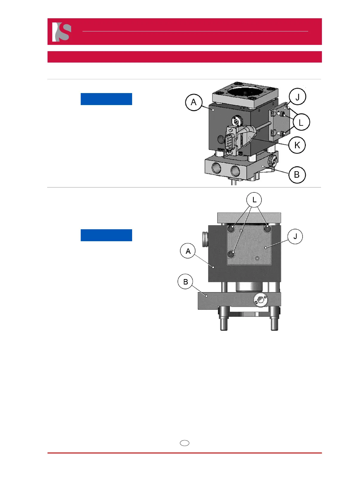
Removal
NOTICE
Before removal and installation
check that the cable (K) is not
pinched and is free of tension.
1) Locate and remove the three M3 screws
(L) on the side of the actuator housing (A).
2) Gently remove the position sensor (J) and
cable (K) making sure not to touch the
printed circuit board underneath.
Doc006385.png.
Installation
NOTICE
When reinstalling make sure the
mating surface is clean of oil and
debris.
1) Place sensor in the correct location and
install the three M3 screws (L).
2) Torque M3 screws to 1.5 Nm.
Doc006421.png
 Loading...