Master Language is English Hot Runner System Installation Guide SVC-17-0001_EN-Rev13
RESTRICTED: Property of Synventive. - 100 - All rights reserved. Errors and omissions excepted
For limited third party distribution based on need and intended use. © 2021 Synventive Molding Solutions
H O T R U N N E R T E C H N O L O G Y
Hot Runner System Installation Guide
Service and Maintenance / Actuator HB Series
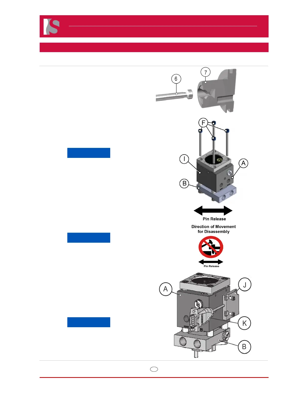
5) Insert valve pin (6) into bushing (7).
6) Slide the actuator so it engages the pin head
slots of the piston.
7) Lubricate the thread of the socket head cap
screws (F) with high temperature assembly
paste (anti-seize compound).
NOTICE
Anti-seize compound is an important
measure to prevent thread corrosion
due to aggressive gasses which could
be released during plastic processing.
8) Secure the actuator with socket head cap
screws (F).
9) Tighten the socket head cap screws (F) in
an “X” pattern (a, d, c, and b). Use a torque
wrench to torque to specications listed in the
table in section 13.
NOTICE
Do not use cylinder housing as
support to get the system into the
mold, (no hammering e.g.)
Doc006243.png
Doc006358.png
8.1.1.10 Position Sensor
The Position Sensor (J) provides the user
with additional information such as if the pins
are in the fully open, fully closed or in an
intermediate position.
NOTICE
The position sensor (J) has a
maximum temperature rating of
150 degrees C and a maximum
cable (K) rating of 200 degrees C.
Doc006386.png.
 Loading...