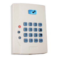
The SYRIS SY110SA is a single-door access controller designed for secure entry management. This device offers a range of functionalities for controlling door access, managing user cards, and setting up various operational parameters. It is presented with a keypad and an integrated bell, available in two color variants (light and dark).
Function Description
The SY110SA primarily functions as a standalone access control unit for a single door. It supports multiple methods for adding and deleting user cards, changing passwords, and configuring various system parameters.
Access Control Modes:
The controller supports four access modes, configurable via the "Access Mode" function key setting:
- Card Only Access Mode (N=1): Requires only a valid card for entry.
- Card or Password Only Access Mode (N=2): Allows entry with either a valid card or a correct personal identification number (PIN).
- Card Plus Card Access Mode (N=3): Requires both a valid card and a correct PIN for entry.
- Password Only Access Mode (N=4): Allows entry with only a correct PIN.
User Management:
- Adding Cards:
- Add one card (User ID + Present Card): Enter a new user ID, then present the card to the reader.
- Add one card (User ID + Card ID): Enter a new user ID and the card's serial number without presenting the card.
- Add multi-cards (First User ID + Last User ID + Present Cards): Enter the first and last user IDs in a range, then present the cards sequentially.
- Auto add card (Auto Search + Present Card): The system automatically searches for an available user ID when a card is presented.
- Deleting Cards:
- Delete one card (User ID): Delete a card by entering its user ID.
- Delete one card (Card ID): Delete a card by entering its serial number.
- Delete multi-cards (First User ID + Last User ID): Delete a range of cards by entering the first and last user IDs.
- Delete one card (Present Card): Delete a card by presenting it to the reader.
- Delete all cards: Clear all stored card data from the controller.
Password Management:
- Change User Password: Users can change their personal PIN by entering the old PIN, then the new PIN twice.
- Change Main Password: The main password, used for logging into the controller, can be changed after logging in. The default main password is "1234".
- Master Card Functionality: The system supports a master card to manage the main password. This function can be enabled or disabled. When enabled, the master card must be presented within 10 seconds after entering the main password to apply changes.
Door Output Control:
The "The use of Door Output" function allows configuration of the door relay action. The setup time (TTT) can be set from 0 to 255 seconds (default 5 seconds). The relay action can be disabled (N=0), controlled by the controller's inner relay (N=1, default), or by an external module relay (N=2). If TTT is set to 0, the door opens/closes when a card is swapped.
Door Bell Functionality:
The "Door Bell" function configures the door bell's operation. The setup time (TTT) can be set from 0 to 255 seconds (default 3 seconds). The door bell function can be disabled (N=0), enabled via the inner relay (N=1), or enabled via an external relay (N=2, default).
Alarm Output Control:
The "Alarm Output Point Setup" function configures the alarm signal output. The setup time (TTT) can be set from 0 to 255 seconds (default 30 seconds). The alarm signal can be stopped (N=0, default), triggered by an inner relay (N=1), or triggered by an external relay (N=2).
Input Point Configuration:
The controller allows configuration of various input points (DI1-DI6) for different functions:
- Push Button Input Point Setup (DI ID, N=0~6): Configures a DI as an open door push button. N=0 disables the function, while N=1~6 enables it for a specific DI.
- Door Sensor Input Point Setup (DI ID, N=0~6): Configures a DI as a door sensor. N=0 disables the function (default), while N=1~6 enables it for a specific DI.
- Door Bell Input Point Setup (DI ID, N=0~6): Configures a DI as a door bell input. N=0 disables the function, while N=1~6 enables it for a specific DI.
- Push Button #2 Input Point Setup (DI ID, N=0~6): Configures a second push button input.
- Door Bell #2 Input Point Setup (DI ID, N=0~6): Configures a second door bell input.
Door State Management:
- Door Always Open (N=0 or 1): N=0 disables this function (default), N=1 enables the door to remain always open.
- Door Forced Open (N=0 or 1): N=0 disables this function (default), N=1 enables door forced open, triggering an alarm output.
- Door Open Timeout (N=0 or 1, TTT): N=0 disables this function (default), N=1 enables door open timeout. If the door remains open longer than the configured TTT (0-255 seconds, default 10 seconds), an alarm may be triggered.
Tamper Switch:
The "Tamper Switch" function (N=0 or 1) allows enabling or disabling the tamper switch. N=0 disables it (default), N=1 enables it. This function uses the controller's inner contact point.
Card Type and Data Format:
- Card Type (N=1~3): Configures the type of card used: N=1 for regular EM Card (default), N=2 for SYRIS card, N=3 for Two Page Card.
- Card Data Bytes Format (N=1~3): Configures the card data format: N=1 for 2 Bytes, N=2 for 3 Bytes (default), N=3 for 4 Bytes.
System Date/Time Setup:
The "Setup Date" function allows setting the current year, month, day, hour, minute, and second.
Important Technical Specifications
- User ID Range: 1 to 2000
- Card ID Length: Maximum 10 digits
- Main Password Length: 1 to 10 digits (default: "1234")
- Personal PIN Length: 1 to 10 digits (e.g., 1234 or 335566 or 1234567890)
- Door Output Setup Time (TTT): 0-255 seconds (default: 5 seconds)
- Door Bell Setup Time (TTT): 0-255 seconds (default: 3 seconds)
- Alarm Output Setup Time (TTT): 0-255 seconds (default: 30 seconds)
- Door Open Timeout (TTT): 0-255 seconds (default: 10 seconds)
- Power Supply: 8V~15VDC
- Inputs (DI): DI1, DI2, DI3 (Bell key/Call Key), DI4, DI5, DI6 (Bell key/Call Key for external keypad reader). All DI functions are fixed and cannot be changed.
- Outputs (DO): DO1 (Controller inner output point), DO2 (External module DO contact).
- Reader Display Status: Includes OK LED, BELL LED, ERROR LED, and various sound indicators for different operational statuses (Normal, Correct, Error, Login, Setup Complete, Await Password, Alarm, Lock, Initializing).
- Timeout Limits:
- Card sense and password entry: 20 seconds. System logs out if timeout or EN is pressed.
- Inactivity: 60 seconds. System logs out if no event occurs.
- Incorrect password attempts: Over three times will lock the controller.
Usage Features
- Keypad Interface: The device features a numerical keypad (0-9), along with dedicated keys for "FUN" (Function), "ADD", "DEL" (Delete), "EN" (Enter), "CLR" (Clear), "OK", and "BELL".
- Login System: To access most configuration functions, the user must first log into the controller using the main password. The default main password is "1234".
- Visual and Auditory Feedback: The device provides clear status indications through LEDs (OK, BELL, ERROR) and audible beeps (short beep, two short beeps, long beep) for various operations and error conditions.
- Simple Wiring Diagram: The manual provides a clear wiring diagram for basic installation, connecting to a door sensor, E.M. Lock, open door push button, and power supply.
- Advanced Wiring Diagram: An advanced wiring diagram is also provided, illustrating connections to an external module (MD120EXT-1S) and SYRIS readers (SYRDS1, SYRDS5, SYRDK5, SYRDL5).
Maintenance Features
- Restore Factory Default: This function clears all setup data, including card data and master card data, restoring the controller to its factory default settings.
- Restore Main Password: This function restores the three sets of main passwords to factory defaults and disables the master card. This can only be performed within 60 seconds of powering up the controller if the initial password has not been changed from "0000000000". The default main password is "1234".
- Initial Password Change: The initial password ("0000000000") can only be changed once, within 60 seconds of power-up, if it has never been modified before.
- Utility Tool Support: For advanced maintenance and configuration, the SY110SA can be connected to a PC using an MDUSB-S-1 and utility tool. This allows for uploading/downloading settings, backing up holder data, I/O data, card numbers, personal passwords, controller parameters, master passwords, and master card numbers.