145 g
This manual is intended as a quick reference installation guide. Please refer to the
control panel manufacturers installation manual for detailed system information.
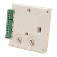
The M200 series of modules are a family of microprocessor controlled interface
devices permitting the monitoring and/or control of auxiliary devices.
M210E SINGLE CHANNEL INPUT MODULE
Provides single channel monitoring of normally open contact re alarm and
supervisory devices.
The M210E has a single tri-colour green/red/yellow LED, which can be set by panel
command to pulse green each time the module is polled. In case of an alarm the
panel can switch the red indicator on continuously. The Yellow LED is controlled by the
module and blinks to indicate an open circuit on the input circuit. This fault indication
is overridden by a panel command to turn the red LED on.
M220E DUAL CHANNEL INPUT MODULE
This is a dual channel module used for the monitoring of normally open contact re
alarm and supervisory devices.
It has two tri-colour LED's, one referring to each channel. Each LED can be set by
panel command to pulse green each time the module channel is polled. In case of
an alarm the panel can switch the red indicator on continuously. The Yellow LED is
controlled by the module and blinks to indicate an open circuit on the input circuit.
This fault indication is always overridden by a panel command to turn the red LED on.
M221E DUAL INPUT, SINGLE OUTPUT MODULE
This module provides dual channel monitoring of normally open contact re alarm
and supervisory devices, and also provides single pole changeover contacts for the
control of auxiliary devices such as re shutters and sounders.
Three tri-colour LED's are provided to indicate the status of each channel.
LED's A and B refer to the two input channels. Each LED can be set by panel
command to pulse green each time the module channel is polled. In case of an alarm
the panel can switch the red indicator on continuously.
LED C refers to the output channel. The LED can be set by panel command to
pulse green each time the channel is polled. The LED will be switched continuously
on green by command from the control panel when the relay contacts are in the
energised state.
The M221E relay contact ratings are 30VDC, 2A or 30VAC, 0.5A (Resistive load).
SPECIFICATIONS
Operating Voltage Range: 15 to 30VDC (Min 17.5VDC for LED operation)
Maximum Standby Current (µA @24 V and 25
o
C): M210E M220E M221E
No Communication 310 340 340
Communication LED blink enabled - 5 secs 510 600 660
Read 16 sec. LED blink 8 sec 410 440 440
LED Current (Red): 2.2mA
LED Current (Yellow): 8.8mA
Maximum rated continuous current with the isolator closed (I
c
max): 1A
Maximum rated isolator switching current (under short circuit) (I
s
max): 1A
Maximum leakage current (I
L
max) with the isolator open (isolated state): 15mA
Maximum series impedance with the isolator closed (Z
c
max): 170 m ohm at 15Vdc
Humidity: 5% to 95% relative humidity (non-condensing)
Maximum Wire Gauge 2.5mm²
INSTALLATION
Note: These modules must only be connected to control panels using compatible
proprietary analogue addressable communication protocols for monitoring and control.
M200 series modules can be mounted in several ways (See Figure 1):
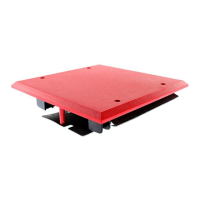
1:1 An M200E-SMB custom low prole surface-mounting box. The SMB Base is
afxed to mounting surface, and then the module and cover are screwed onto
the base using the two screws supplied. Box dimensions: 132mm(H) x 137mm(W)
x 40mm(D)
1:2 An M200E-DIN Adaptor allows mounting onto standard 35mm x 7.5mm "Top Hat"
DIN rail inside a control panel or other suitable enclosure. Push module into adaptor
bracket until it clips into place. Locate top clip over DIN rail and rotate bottom down
to clip into place. To remove, lift up, then rotate top away from the rail.
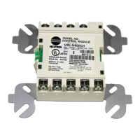
1:3 An M200E-PMB Panel Mount Bracket allows the module to be mounted directly
into a panel or other suitable enclosure. Adaptor bracket is mounted directly into
panel using 2 x M4 Pan head screws. Module is pushed into adaptor until it clips
into place.
Wiring to all series M200 modules is via plug in type terminals capable of supporting
conductors up to 2.5mm²
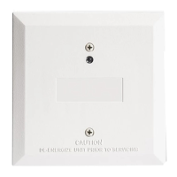
CAUTION
Disconnect loop power before installing modules or sensors.
The module address is selected by means of rotary decade address switches (see
Figure 4). A screwdriver should be used to rotate the wheels to select the desired
address, either from the front or the top of the module.
For modules having more than one channel, the address selected will refer to the rst
input channel, the module will automatically assign the next one or two addresses
as appropriate to the second input channel and output channel. As a result, address
159 will be invalid for dual channel modules, and addresses 158 and 159 are invalid
for three channel modules. If these addresses are selected, no response will be seen
from the module (not relevant if using Advance Protocol - consult panel manufacturer
if in doubt).
Fig./Abb. 1
1:1 M200E-SMB
1:2 M200E-DIN
1:3 M200E-PMB
M210E M220E M221E
INSTALLATION INSTRUCTIONS - M210E / M220E
INPUT MODULES, M221E INPUT /OUTPUT MODULE
EN
Fig./Abb. 4
Fig./Abb. 3
a
b
c
d
e
f
g
a
b
c
d
e
f
Fig./Abb. 5
+
(i)
(ii)
(iii)
M221E
M210E
M220E
A
B
C
X
1
0
X
1
6
6
23 mm
I 56- 1766- 020
Fig./Abb. 2
g
ABC
x10
x1
A B
1
0
0
1
2
3
4
5
6
7
8
9
10
11
12
13
14
15
0
1
2
3
4
5
6
7
8
9
1
2
3
4
5
6
7
8
9
10
11
12
94 mm
83 mm
93
mm
f