D500-19-00 1 I56-762-01
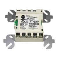
M502M Two-wire Conventional
Detector Interface Module
INSTALLATION AND MAINTENANCE INSTRUCTIONS
A Division of Pittway
3825 Ohio Avenue, St. Charles, Illinois 60174
1-800-SENSOR2, FAX: 630-377-6495
Before Installing
This information is included as a quick reference installa-
tion guide. Refer to the appropriate installation manual for
detailed system information. If the modules will be in-
stalled in an existing operational system, inform the opera-
tor and local authority that the system will be temporarily
out of service. Disconnect power to the control panel before
installing the modules.
NOTICE: This manual should be left with the owner/user
of this equipment.
General Description
The M502M Interface Module allows intelligent panels to
interface and monitor two-wire conventional smoke detec-
Specifications
Temperature: 32° to 120° F (0° to 49° C)
Humidity: 10% to 93% Noncondensing
Weight: .5 lbs (232 g)
Dimensions: 4
1
/2" H, 4" W, 1
1
/4" D (Mounts to 4" square by 2
1
/8" deep electrical boxes.)
Test Features: Magnetically activated reed switch.
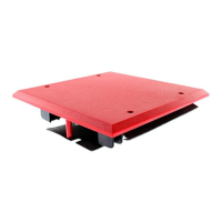
Accessories: SMB500 Surface Mount Box for 500 series modules
M02-04-00 Test Magnet for testing devices
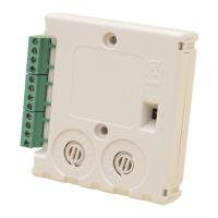
Communication Line – Terminals 1 & 2
Voltage: 15 – 32 VDC
Current: 200
µ
A Max @ 24 VDC, no communication
1.3 mA Max (Style D enabled)
5.1 mA Max 24V (LED latched on)
Loop Impedance: 40 Ω Max
External Power Supply Requirements – Terminals 3 & 4
Voltage: 17.6 – 28.2 VDC (filtered, regulated, and power-limited)
Ripple: 100mV RMS Max
Current: 92 mA per module
(Power must be interrupted to reset detectors. The interface module must have a minimum of 15 VDC at terminals 3 and 4
to function properly. Ground fault detection must be accomplished by the control panel.)
Initiating Device Circuit (IDC) – Terminals 6, 7, 8, & 9
Voltage: 12.5 to 30.3 VDC (Ripple: 100mV RMS Max)
Current: 92 mA Max
IDC Loop Impedance: 25 Ω Max
Standby Current: 10 mA Max @ maximum IDC voltage
Detector Current in Standby: Up to 2.4 mA
Alarm Current: 20 mA minimum
Style: Style B (class B) / Style D (class A)
EOL Resistance: 3.9K ohm nominal
(Detector loop current is sufficient to ensure operation of one alarmed detector per zone.)
tors. All two-wire detectors being monitored must be UL
compatible with the module.
The module is addressed through the communication line
of intelligent systems. When the module is interrogated, it
transmits the status of one zone of two-wire detectors to an
intelligent control panel. Status conditions are reported as
normal, open, or alarm. The interface module supervises
the zone of detectors and the connection of an external
power supply.
Two rotary decade switches allow setting module addresses
from 00–99. A status LED indicator is provided and is con-
trolled by code command from the control panel. The mod-
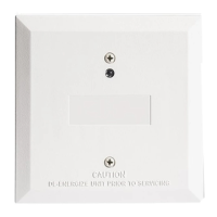
ule provides a magnetically activated test switch for testing
Technical Manuals Online! - http://www.tech-man.com