D500-19-00 2 I56-762-01
Compatible Two-wire System Sensor Smoke Detectors for Use with M502M with Zone Identifier A:
Detector Compatability Detector Base Base Max
Model ID Type Model Identifier Detectors
1451 A Ionization B401/B A 20
2451 A Photoelectric B401/B A 20
2451TH A Photoelectric with Thermal B401/B A 20
1400 A Ionization N/A — 20
2400 A Photoelectric N/A — 20
2400TH A Photoelectric with Thermal N/A — 20
1100 A Ionization N/A — 20
1151 A Ionization B110LP/B401 A 20
2100 A Photoelectric N/A — 20
2100T A Photoelectric with Thermal N/A — 20
2151 A Photoelectric B110LP/B401 A 20
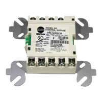
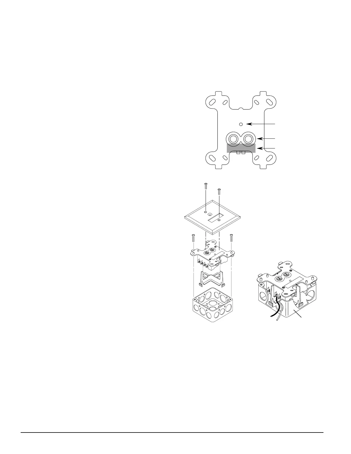
Figure 1. Module controls and indicators:
ISOLATED
QUADRANT
Figure 2B:
A78-2611-00
the module’s electronics and connections to the control
panel (see Figure 1).
Compatibility Requirements
To insure proper operation, this module shall be connected
to compatible intelligent control panels only.Conventional
two-wire smoke detectors must be UL compatible with the
interface module. A list of compatible two-wire convention-
al detectors is below.
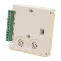
Package Contents
The interface module includes the following items:
(1) Two-wire interface module
(1) 3.9K ohm end-of-line resistor (A2143-10)
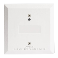
(1) Off-white cover plate
(1) Screw pack for cover plate
Mounting
The M502M Interface Module mounts directly to 4 inch
square electrical boxes as shown in Figure 2. The box must
have a minimum depth of 2-1/8 inches.
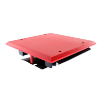
Wiring
NOTE: All wiring must conform to applicable local codes,
ordinances and regulations. When using control
modules in nonpower limited applications, the Sys-
tem Sensor CB500 Module Barrier must be used to
meet UL requirements for the separation of power-
limited and nonpower-limited terminals and wir-
ing. The barrier must be inserted in a 4"x4"x2
1
/
8
"
junction box, and the control module must be
placed into the barrier and attached to the junction
box (Figure 2A). The power-limited wiring must be
placed into the isolated quadrant of the module
barrier (Figure 2B).
1. Install module wiring in accordance with the job draw-
ings and appropriate wiring diagrams (Figures 3 – 5).
2. Set the address on the module per job drawings.
3. Secure module to electrical box (supplied by installer),
as shown in Figure 2A.
Testing
The M502M Interface Module can be tested with a test
magnet available from System Sensor (M02-04-01- see Fig-
ure 1). The magnet test checks the module’s electronics
and connections to the control panel. Interfaced two-wire
detectors must be tested independently. Test two-wire de-
tectors per manufacturer’s installation instructions.
STATUS LED
ROTARY DECADE
ADDRESS SWITCHES
MAGNET TEST
POSITION
27
0
1
3
4
5
6
8
9
27
0
1
3
4
5
6
8
9
A78-2318-00
A78-2610-00
Figure 2A. Mounting module with barrier:
Technical Manuals Online! - http://www.tech-man.com
 Loading...