D500-19-00 4 I56-762-01
© System Sensor 1996
Three-Year Limited Warranty
System Sensor warrants its enclosed module to be free from defects in ma-
terials and workmanship under normal use and service for a period of
three years from date of manufacture. System Sensor makes no other ex-
press warranty for this module. No agent, representative, dealer, or em-
ployee of the Company has the authority to increase or alter the
obligations or limitations of this Warranty. The Company’s obligation of
this Warranty shall be limited to the repair or replacement of any part of
the module which is found to be defective in materials or workmanship
under normal use and service during the three year period commencing
with the date of manufacture. After phoning System Sensor’s toll free
number 800-SENSOR2 (736-7672) for a Return Authorization number,
send defective units postage prepaid to: System Sensor, Repair Depart-
ment, RA #__________, 3825 Ohio Avenue, St. Charles, IL 60174. Please
include a note describing the malfunction and suspected cause of failure.
The Company shall not be obligated to repair or replace units which are
found to be defective because of damage, unreasonable use, modifica-
tions, or alterations occurring after the date of manufacture. In no case
shall the Company be liable for any consequential or incidental damages
for breach of this or any other Warranty, expressed or implied whatsoever,
even if the loss or damage is caused by the Company’s negligence or fault.
Some states do not allow the exclusion or limitation of incidental or conse-
quential damages, so the above limitation or exclusion may not apply to
you. This Warranty gives you specific legal rights, and you may also have
other rights which vary from state to state.
A78-2396-06
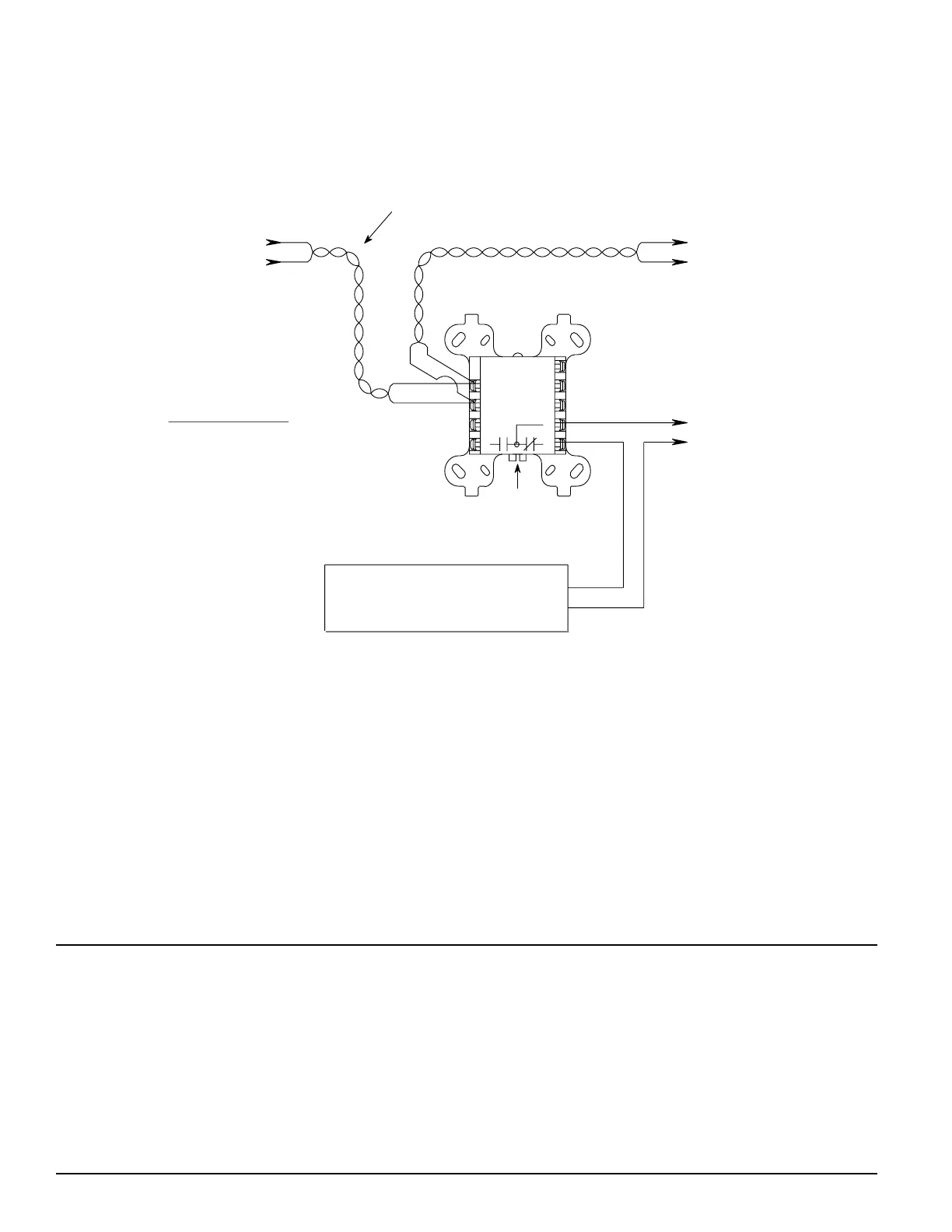
1 (–)
2 (+)
MODULE
(+)
(–)
CONTROL
9
8
7
6
5
3
4
J1 & J2
BREAK TABS J1 & J2
TO ENABLE FORM 'C' MODE
RELAY CONTACT RATINGS:
RESISTIVE:
INDUCTIVE:
PILOT DUTY:
2 A @ 30 VDC
1 A @ 30 VDC (.6 PF)
.6 A @ 30 VDC (.35 PF)
.3 A @ 110 VDC (.35 PF)
.3 A @ 120 VAC (.35 PF)
FROM PANEL OR
(+)
(–)
SEE REQUIREMENTS ON PAGE 3
DC POWER SUPPLY, LISTED FOR FIRE
PROTECTION WITH BATTERY BACKUP
(+)
(–)
(MONITOR LOSS OF INPUT POWER)
CONTACTS ARE SHOWN IN STANDBY.
CONTACTS MAY HAVE SHIFTED TO ALARM
TO NEXT
(+)
(–)
DEVICE
CONNECT MODULES TO LISTED
COMPATIBLE CONTROL
PANELS ONLY.
TWISTED PAIR
IS RECOMMENDED
(+)
(–)
DURING SHIPPING. DO NOT APPLY
POWER TO THE CIRCUITS THE MODULE
PREVIOUS DEVICE
SWITCHED RISER
CIRCUIT FOR
INTERFACE MODULES
TC810A CONTROL
MODULE IS NOT REQUIRED
IF SWITCHABLE POWER
IS AVAILABLE.
COMMUNICATION LINE
CONTROLS UNTIL THE MODULE IS
CONNECTED TO AND ACCEPTED BY THE PANEL.
32 VDC MAX.
TERMINAL WIRING MUST BE POWER LIMITED.
Figure 5. M500C series control module switching a power supply (controls switched 24 VDC external power
to M502M)
Technical Manuals Online! - http://www.tech-man.com
 Loading...