D900-01-00 3 I56-650-16
LIGHT
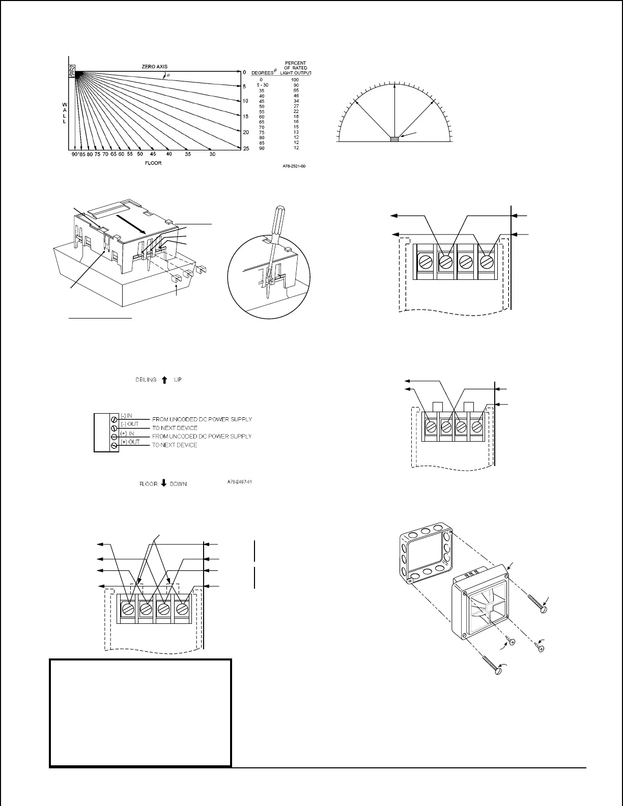
0˚
–45˚
45˚
90˚ –90˚
1. Complete field wiring. (See Fig. 5)
2. Screw sounder to box with screw A.
3. Fill remaining holes with screw B.
Degrees % of Rating
0 100
5 - 25 90
30 - 45 75
50 55
55 45
60 40
65 35
70 35
75 30
80 30
85 25
90 25
From
panel or
previous
device
To Next
Device
or EOL
– VDC
+ VDC
Note: Use uncoded supply only.
(–)
IN OUT
STROBE
ONLY
(–)
IN OUT
(+)
IN OUT
STROBE
ONLY
(+)
IN OUT
(-)
IN OUT
STROBE
ONLY
(-)
IN OUT
(+)
IN OUT
STROBE
ONLY
(+)
IN OUT
From
panel or
previous
device
To Next
Device
or EOL
- VDC
+ VDC
MA12/24D
A
B
B
A
BB-STD
A78-1137-03
A78-1137-29
A78-1137-00
A78-2167-00
Figure 1. Vertical and horizontal light distribution:
CLIP
STORAGE
CLIPS REMOVED OR
ADDED TO SELECT
DESIRED TONE.
COVER SLOT
TAB A
TAB B
TAB C
FOR STORING UNUSED CLIPS:
SLIDE COVER BACK TO ALIGN COVER SLOT
WITH CLIP STORAGE POST.
SLIDE COVER
FOR CLIP STORAGE
USE A
SMALL-
BLADED
SCREWDRIVER
TO REMOVE
CLIPS
TONE
SELECTION TABS
Figure 2: Figure 3. Multi-alert sounder:
Figure 4. Strobe:
Figure 5. Multi-alert sounder and strobe operating in
tandem:
From
panel or
previous
device
To Next
Device
or EOL
– VDC
+ VDC
+ VDC
– VDC
STROBE
SOUNDER
(–)
IN OUT
STROBE
ONLY
(–)
IN OUT
(+)
IN OUT
STROBE
ONLY
(+)
IN OUT
Non-
Coded
Supply
Can Be
Coded
Supply
Caution: Break off P.C.B. Tabs
Figure 6. Multi-alert sounder and strobe operating
independently:
A78-1137-01
Figure 7. Sounder surface mount:
Screw types used in figure 9 to 15
A = 8-32x1-7/16" Slot
B = #8 Sheet Metal Phillips
C = 8-32x1" Phillips
D = #8 Sq. Nut
E = 8-32x5/8" Slot
F = 8-32x2-3/4" Slot
G = 6-32x5/8" Slot
Technical Manuals Online! - http://www.tech-man.com