D900-11-00 1 I56-759-07
MA12/24EH* Electronic Sounder;
SS12LO, SS12M, SS24LO*, SS24M*
Electronic Strobes; MAEH12LO,
MAEH12M, MAEH24LO*, MAEH24M*
Sounder/Strobes Combined
*ULC models add suffix “A”; available in 24V models only.
INSTALLATION AND MAINTENANCE INSTRUCTIONS
A Division of Pittway
3825 Ohio Avenue, St. Charles, Illinois 60174
1-800-SENSOR2, FAX: 630-377-6495
NOTICE: This manual should be left with the owner/user of this
equipment.
General Description
The National Fire Protection Association has published standards
and recommended practices for the installation and use of the
listed appliances. It is recommended that the installer be familiar
with these requirements, with local codes, and any special re-
quirements of the authority having jurisdiction.
The electronic Multi-Alert sounder and the signaling strobe are in-
tended to be connected to the alarm indicating circuit of a listed
fire alarm control panel. Both are compatible with DC line super-
vision. The model MA12/24EH is suitable for connection to either
a 12 or 24 volt panel. Models SS24LO, SS24M, MAEH24LO and
MAEH24M require 24 volt panels; models SS12LO, SS12M,
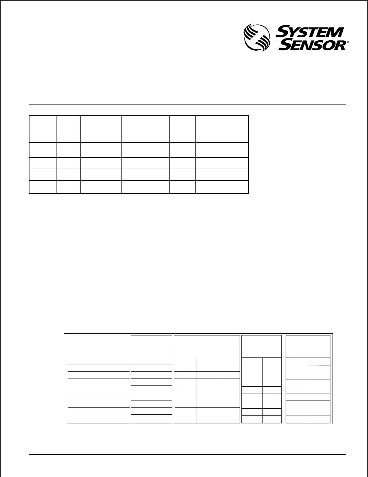
Sound (Hz) Clips on Tabs Current (mA) ( Note 1) Output (dBA) UL (dBA)
( Note 4) DC Regulated/ (Note 2) Ratings
FWR Unfiltered (Note 3)
12V 24V 30V 12V 24V 12V 24V
Fast Whoop ABC 21/40 38/56 46/72 85 92 79 85
800 Continuous BC 15/24 28/45 35/55 87 93 79 85
800/1000 Fast-Dual AC 17/32 34/46 43/58 85 92 79 85
Chirp AB 19/23 35/56 43/64 89 90 79 85
2400 Continuous C 21/31 38/59 46/73 85 94 79 85
Bell B 13/19 23/33 27/41 85 91 75 82
Laser A 17/24 34/47 43/60 85 92 79 85
Electro-Mechanical NONE 15/27 30/47 38/59 85 92 79 85
Model Supply Operating Operating Current Peak Minimum Output
Voltage Current from from Rectified Current @ 100% Viewing
Regulated Supply Unfiltered Supply Angle (see Fig. 3)
(VDC) (mA) (mA, RMS) (mA) (Candela)
SS12LO 12-17 50 80 550 1.5
SS24LOA 22.5-30 (.22@-35
o
C)
SS12M 12-17 180 300 440 15
SS24MA 22.5-30 (5.9 @-35
o
C)
SS24LO 22.5-30 25 45 225 1.5
(.22@-35
o
C)
SS24M 22.5-30 75 125 450 15
(5.9 @-35
o
C)
Table 2. Sound output and current ratings for the MA12/24EH:
Table 1. SS12/24 electrical and light ratings:
Note 4: See Figure 4 for tab clip removal & storage.
Note 5: All horn or combination strobe models can be powered
using full wave rectified unfiltered supplies.
Under no circumstances can the
input voltage:
for the SS24 or MAEH24 exceed
33 VDC or be less than 18 VDC.
for the SS12 or MAEH12 ex-
ceed 18.7 VDC or be less than
9.6 VDC.
for the MA12/24EH exceed 33
VDC or be less than 9.6 VDC.
Note 1: With 1.5 cd strobes add 50 mA @ 12V, 25 mA @ 24V.
With 15 cd strobes add 180 mA @ 12V, 75 mA @ 24V.
Note 2: Sound output measured in anechoic room at 10 feet.
Note 3: Sound output measured in UL reverberant room.
MAEH12LO and MAEH12M require 12 volt panels. Horn, strobe,
or combination strobe models may be used with panels that have
full wave rectified, unfiltered supplies. The MA12/24EH sounder
and MAEH12/24 sounder/strobes are suitable for outdoor appli-
cations (–35°C to 66°C) when used with a Weatherproof Back
Box (Model WBB) as tested by UL. In Canada, rigid steel conduit
must be used when installing the Weatherproof Back Box. Light
output for the SS12LO, SS24LO, MAEH12LO and MAEH24LO is
1.5 cd min @100% viewing angle. Light output for the SS12M,
SS24M, MAEH12M, and MAEH24M is 15 cd min @100% viewing
angle (See Figure 3).
There are eight different sounds which can be selected on the
electronic sounder by adding or removing tab clips (see Figure 4).
The sound selected will determine the maximum current and
sound power output per device. See Table 2 for these values.
Technical Manuals Online! - http://www.tech-man.com
 Loading...