D770-15-00 1 I56-984-02
PSP1 Plug-in Special Purpose
Supervisory Switch
INSTALLATION AND MAINTENANCE INSTRUCTIONS
A Division of Pittway
3825 Ohio Avenue, St. Charles, Illinois 60174
1-800-SENSOR2, FAX: 630-377-6495
Specifications
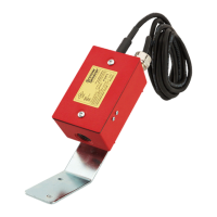
Dimensions: 4.73″ L x 2.94″ W x 2.21″ D (12 cm L x 7.5 cm W x 5.6 cm D)
With bracket – 8.5″ L (21.5 cm L)
Weight: 1.7 lbs. (.774kg)
Enclosure Rating: Cast-aluminum rain-tight outlet box, Indoor/Outdoor NEMA 3
Tamper Protection: Cover tamper switch and tamper-proof cover screws
Operating Voltage: 6/12/24 volts AC/DC
Maximum Operating Current: 250 mA
Operating Temperature: -4˚ F to 149˚ F (-20˚ C to 65˚ C)
Important
Please Read Carefully and Save
This instruction manual contains important information
about the installation and operation of this supervisory
switch. This manual should be left with the owner/user of
this equipment.
General Information
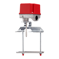
The unit is intended for supervision of non-rising stem gate
valves and other valves that cannot be monitored by con-
ventional supervisory switches. Turning the valve wheel
will pull the plug out of the jack and close a set of normally
open contacts. A lockout will prevent reinsertion and re-
quire removal of the cover. Tamperproof screws are pro-
vided for the cover. Removal of cover, or cutting of cord or
ground faults will cause an open circuit. The device should
be wired to the trouble circuit of a fire alarm control panel.
Installation
1. Choose a location near the valve (safe from flooding)
and mount the bracket to the wall.
2. Rotate the box on the bracket until the plug faces the
valve. The plug must also point downward. Tighten the
locknut on the pivot.
3. Turn the valve to the full-open position. Insert the plug
into the jack. Tightly loop the 8-ft. waterproof cable
through the valve wheel and back into the box through
the cable clamp. Close valve to check that plug pulls out
and then turn valve back to full-open position. Cut the
cord to the minimum length required to make the con-
nections within the box.
4. For all exterior applications, use
1
/2″ NPT, listed liquid-
tight conduit connectors.
5. Wire the device as per the circuit diagrams shown (see
Figures 2-5). Trim the unused black wire flush with the
cable casing and cap the red wire of the cover tamper
switch.
6. If a longer cable is required, use SJOW A 16-2, two con-
ductor 16-gauge stranded rubber-jacketed cable.
7. Using the adhesive pad and wire tie provided, dress the
wires away from the lock-out mechanism.
8. When installing the cover, make sure the O-rings are in
place on the cover screws beneath the cover.
Figure 1. PSP1:
D770-15-00 4 I56-984-02
© System Sensor 1998
Three-Year Limited Warranty
System Sensor warrants its enclosed supervisory switch to be free from
defects in materials and workmanship under normal use and service for a
period of three years from date of manufacture. System Sensor makes no
other express warranty for this supervisory switch. No agent, representa-
tive, dealer, or employee of the Company has the authority to increase or
alter the obligations or limitations of this Warranty. The Company’s obli-
gation of this Warranty shall be limited to the repair or replacement of any
part of the supervisory switch which is found to be defective in materials
or workmanship under normal use and service during the three year pe-
riod commencing with the date of manufacture. After phoning System
Sensor’s toll free number 800-SENSOR2 (736-7672) for a Return Authori-
zation number, send defective units postage prepaid to: System Sensor,
Repair Department, RA #__________, 3825 Ohio Avenue, St. Charles, IL
60174. Please include a note describing the malfunction and suspected
cause of failure. The Company shall not be obligated to repair or replace
units which are found to be defective because of damage, unreasonable
use, modifications, or alterations occurring after the date of manufacture.
In no case shall the Company be liable for any consequential or incidental
damages for breach of this or any other Warranty, expressed or implied
whatsoever, even if the loss or damage is caused by the Company’s negli-
gence or fault. Some states do not allow the exclusion or limitation of inci-
dental or consequential damages, so the above limitation or exclusion may
not apply to you. This Warranty gives you specific legal rights, and you
may also have other rights which vary from state to state.
Technical Manuals Online! - http://www.tech-man.com