D440-03-00 1 I56-758-06
RTS451KEY(A) Remote Test Station
INSTALLATION AND MAINTENANCE INSTRUCTIONS
3825 Ohio Avenue, St. Charles, Illinois 60174
1-800-SENSOR2, FAX: 630-377-6495
NOTICE: This manual shall be left with the owner/user of
this equipment.
General Information
The System Sensor RTS451KEY(A) is an automatic fire de-
tector accessory designed to test remotely located duct and
beam detectors. For 4-wire detectors, the RTS451KEY fea-
tures a multi-colored LED that alternates between steady
green and red. Green indicates power and that the detector
board is in place. Red indicates alarm. For 2-wire detectors,
the LED will show red for alarm. Consult the detector in-
stallation instructions for additional information.
The National Fire Protection Association has published
codes, standards, and recommended practices for the in-
stallation and use of this product. It is recommended that
the installer be familiar with these requirements, with local
codes, and any special requirements of the local authority
having jurisdiction.
RTS451 Contents
1 RTS451KEY(A) remote test station
1 #4 screw for mounting bracket
1 screw pack (2 mounting screws)
2 Keys
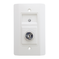
A78-2591-00
Figure 1. RTS451KEY:
Specifications
Dimensions: 4.6” H x 2.75” W x 1.8” D
Weight: 0.22 Lbs.
Power Requirements
Power LED (Green): 14 – 35 VDC, 12 mA maximum
Alarm LED (Red): 2.8 – 32 VDC, 7.5 mA maximum
Total Current: 103 mA maximum
Alarm Response Time: 40 seconds maximum
Te mperature: –10°C to 60°C (14°F to 140°F)
Humidity: 95% relative humidity, noncondensing
Operation
Test Function
Insert the key and turn clockwise to the “TEST” position.
Alarm Indication
With the key in the “TEST” position, some time will elapse
(40 seconds maximum) depending on the detector type, be-
fore the alarm indicating LED will turn red.
Reset Function
Turn the key counterclockwise to the “RESET” position and
hold. The LED should turn off. Then, turn the key back to
the “NORMAL” position and remove. The RTS451KEY is
capable of resetting only certain models of detectors. Refer
to the detector installation instructions for additional
information.