D900-08-00 2 I56-732-04
84
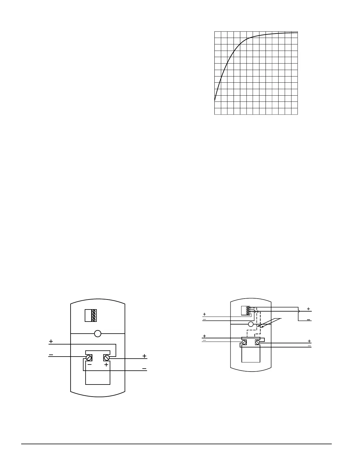
85
86
87
88
89
90
10 12 14 16 18 2 0 2 2
Voltage
dBA output
Figure 2:
From
Control
Panel
or
Previous
Device
To
Next
Device
or
EOL
Figure 3. Operating horn and strobe in tandem:
Polarity shown in alarm condition. Polarity is reversed in
supervisory condition.
A78-2663-00
From
Control
Panel
or
Previous
Device
Note: Remove paper
shield; cut and
remove red and
black wires between
the horn and strobe.
When finished wiring,
place paper shield
back on unit.
To
Next
Device
Blk
Cut and
Remove for
Independent
Operation
Red
Figure 4. Operating horn and strobe independently:
Polarity shown in alarm condition. Polarity is reversed in
supervisory condition.
A78-2664-00
Greater than 90 dBA measured in anechoic room at 10 feet,
24 volts (see Figure 2 for other voltages); 79 dBA minimum
measured in UL reverberant room @ 12V and 82 dBA @
24V.
NOTE: All models can be powered using full wave recti-
fied unfiltered supplies. Under no circumstances
can PS24ADA series devices input voltage exceed
33 VDC or be less than 16 VDC (16-33Vrms for full-
wave rectified, unfiltered supplies). Under no cir-
cumstances can a PS12ADA series device input
voltage exceed 18.7 VDC or be less than 9.6 VDC
(9.6 - 18.7Vrms for full-wave rectified, unfiltered
supplies).
Installation
A. General:
Phillips head screws are used to attach PS12/24ADA to
semi-flush plate or the electrical outlet box. Slotted head
screws are used to attach semi-flush plate to outlet box.
See Figures 3 and 4 for wiring methods.
NOTE: Do not loop wires under the terminal screw. Wires
connecting the device to the panel must be broken
at the device terminal connection in order to
maintain electrical supervision.
The PS12/24ADA is designed for wall mounting ONLY.
It is intended for mounting to a standard 2-1/2" deep
single gang box which allows sufficient clearance for
conduit entrance.
All strobes must be mounted so that the top of the lens is
24 inches (61cm) below ceilings or as required by the
authority having jurisdiction.
B. Sounder/Strobe combination mounting:
1. Surface Mount: (See Figure 5)
2. Semi-Flush Mount: (See Figures 6 and 7)
3. Semi-Flush Mount with Plaster Ring or Double Gang
Box: (See Figure 8)
Installation procedures must conform to all applicable codes
and the requirements of the authority having jurisdiction.
NOTE: The rated output of the sounder is specified at 10
feet. It cannot be assumed that the output will
meet the NFPA standard of 15 dB over ambient
noise at all locations within a room. Additional
sounders may be needed to ensure sound output
level complies with NFPA requirements.
Technical Manuals Online! - http://www.tech-man.com
 Loading...