D900-09-00 1 I56-757-02
RP12/24ADA Series Retrofit
Strobes for Fire Protective
Signaling Systems
INSTALLATION AND MAINTENANCE INSTRUCTIONS
A Division of Pittway
3825 Ohio Avenue, St. Charles, Illinois 60174
1-800-SENSOR2, FAX: 630-377-6495
NOTICE: This manual should be left with the owner/user
of this equipment.
General Description
The National Fire Protection Association has published
standards and recommended practices for the installation
and use of the listed appliances. It is recommended that the
installer be familiar with these requirements, with local
codes, and any special requirements of the local fire au-
thority having jurisdiction.
The RP12/24ADA series retroplates are ADA compliant (75
and 110 cd models) signaling devices and designed for use
in existing or new installations. They are a low-cost alterna-
tive to replacing a sounder with a new sounder/strobe.
This signaling strobe is intended to be connected to the
alarm indicating circuit of a UL-listed fire alarm control
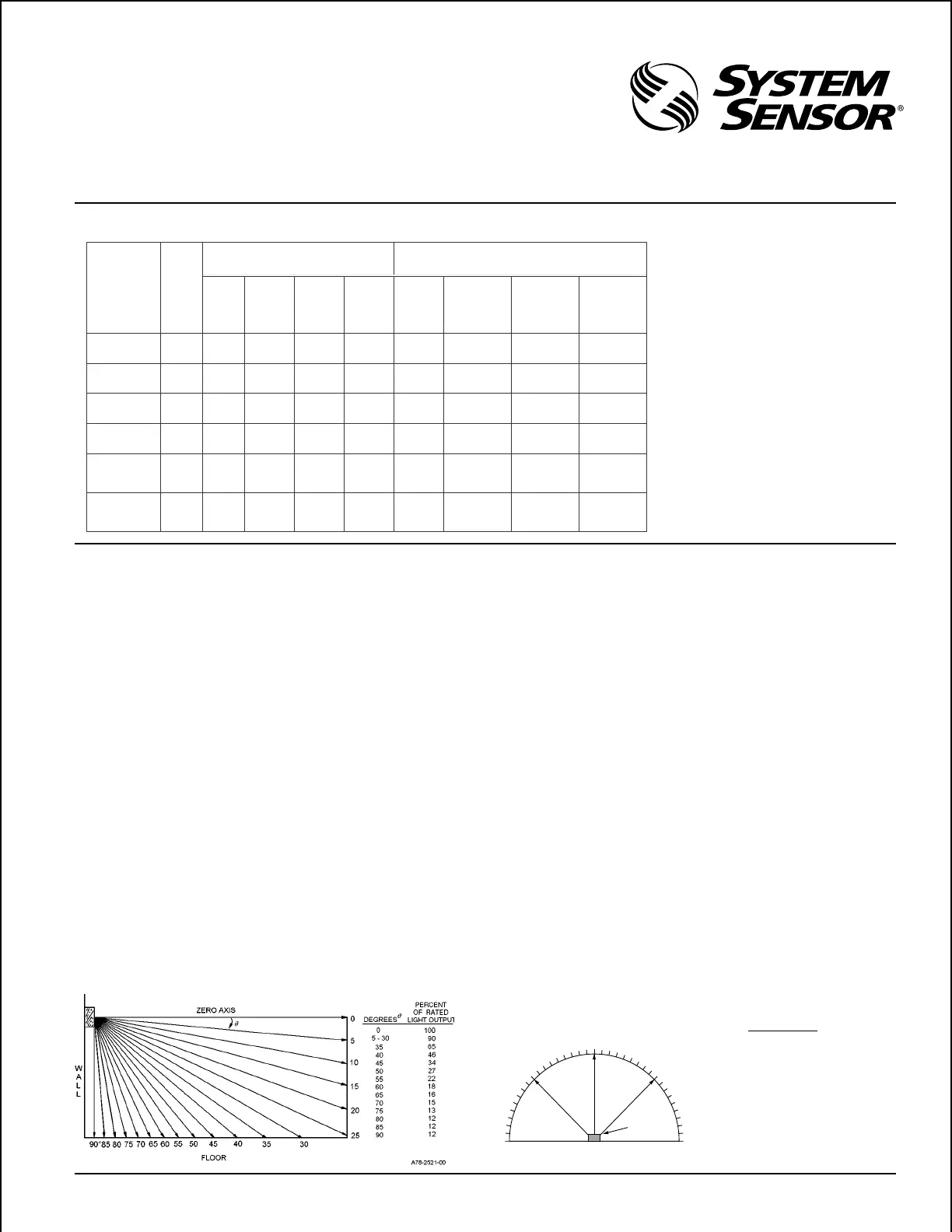
Figure 1. Vertical and horizontal light distribution:
LIGHT
0˚
–45˚
45˚
90˚ –90˚
Percent of
Degrees Rating
0 100
5 - 25 90
30 - 45 75
50 55
55 45
60 40
65 35
70 35
75 30
80 30
85 25
90 25
Table 1. RP12/24ADA Series electrical ratings:
Model Supply
Voltage
Range
Operating Current from Regulated Supply Operating Current from Full-Wave Rectified Unfiltered
Supply
Average
Operatin
Current
Peak
Current
(mA)
20/30V
Peak
Current
(mA)
10.5V/17V
Inrush
Current
(mA in
access of
Peak)
Average
Operating
Current
(mArms)
Peak Current
(mA)
20Vrms/30Vrms
Peak Current
(mA)
10.5Vrms/17Vrms
Inrush Current
(Amps in
excess of Peak)
RP24110ADA
RP24110ADAW
20-30V 210 470/500 - 0 245 400/500 - 0.08
RP2475ADA
RP2475ADAW
20-30V 170 385/400 - 0 200 320/370 - 0.04
RP2415ADA
RP2415ADAW
20-30V 75 160/180 - 0 90 275/290 - 0.02
RP1215ADA
RP1215ADAW
10.5-17V 170 - 360/380 0 200 - 330/380 0.02
RP241575ADA
RP241575ADAW
20-30V 93 210/220 -- 0 120 275/290 -- 1
RP121575ADA
RP121575ADAW
10.5-17V 225 -- 510/560 0 270 -- 500/530 0.02
NOTE: In-rush current du-
ration is less than
20 microseconds
(0.00002 seconds).
panel. It is compatible with DC line supervision. Models
RP2415ADA, RP2475ADA, RP24110ADA, and
RP241575ADA require 24 volt panels. Models RP1215ADA
and RP121575ADA require 12 volt panels. Panels may have
full-wave rectified, unfiltered power supplies. The strobes
produce one flash per second (nominal) with continuous
nominal voltage applied.
The rated light output of the RP2415ADA, RP1215ADA,
RP241575ADA, and RP121575ADA is 15 cd (see Figure 1).
The rated light output of the RP2475ADA is 75 cd (please
see Figure 1).
The rated light output of the RP24110ADA is 110 cd (please
see Figure 1).
NOTE: The light output at 0° viewing angle for RP12/
241575ADA models is 75 cd (see Figure 1).
Technical Manuals Online! - http://www.tech-man.com
 Loading...