D900-09-00 4 I56-757-02
© System Sensor 1996
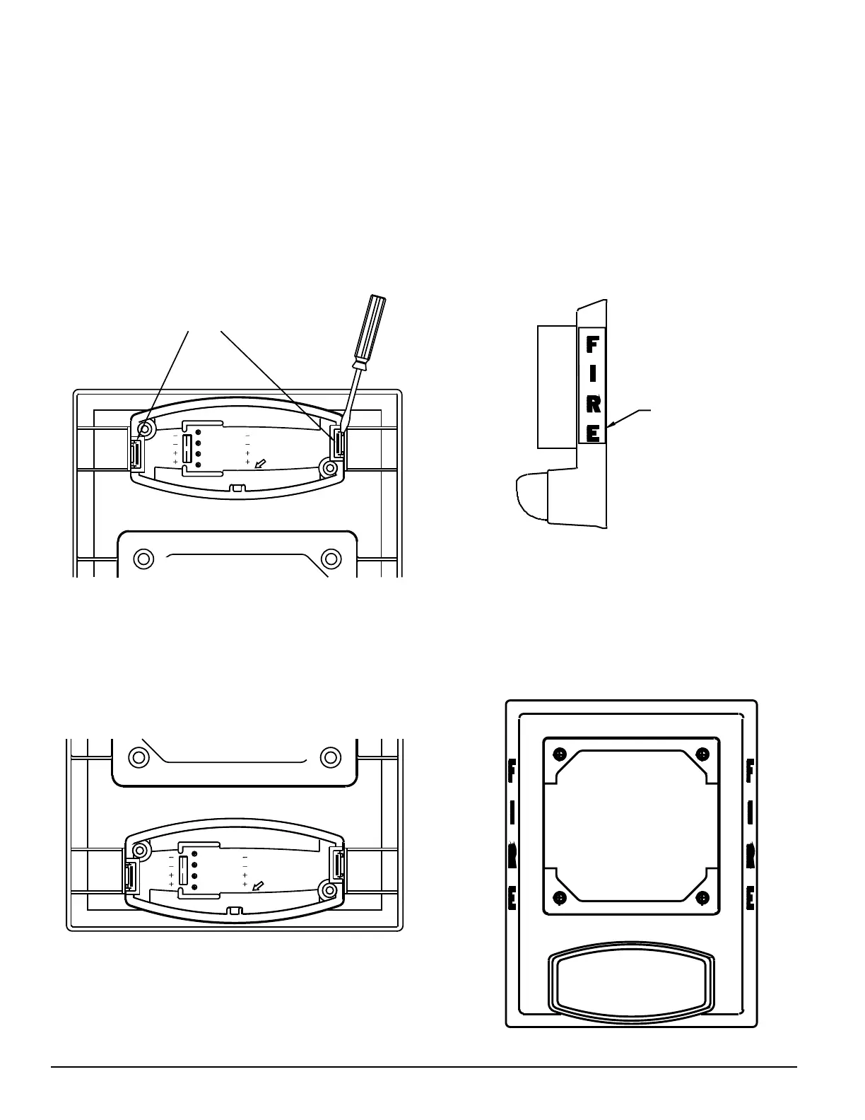
Inverted Installation
1. Remove strobe unit by inserting a screwdriver behind the
locking tabs, and gently pry the tabs inward (see Figure 5).
2. Carefully pull the strobe unit out from the back of the
backplate.
3. Rotate the backplate 180 degrees with sounder on top
(see Figure 6).
Note: Proper lens orientation.
Label placement
)
)
(
(
)(
)(
OUT
IN
OUT
IN
WIRE
STRIP
GAGE
IN
OUT
IN
OUT
()
()
)(
()
Locking Tabs
Figure 5. Remove strobe: Figure 6. Rotate backplate 180°:
Figure 8. Final inverted unit:
OUT
OUT
(
(
(
(
)(
(
IN
(
)
)
IN
(
)
OUT
OUT
IN
IN
)
)
)
STRIP
GAGE
WIRE
)
Figure 7. Snap strobe back into place:
4. Snap strobe unit back into place noting the alignment of
the text on the back of the strobe unit (see Figure 7).
5. Place new FIRE label over old print using the backplate
edge for alignment (see Figure 6).
6. Refer to Figure 4 on page 3 for mounting procedures.
Technical Manuals Online! - http://www.tech-man.com
 Loading...