Systemair NOVA drive 370
|
9
5.2 Electrical Installation
When installing the product, means of power disconnection shall be incorporated in the fixed wiring in order to ensure
all pole disconnection from supply mains. A fuse shall be installed in front of the inverter, with the following character-
istic: max C16.
5.2.1 Earthing / Grounding
Ground the drive properly. Refer to Figure 5 for ground connector marked with PE for its placement. Use the mounting
torque specified in section 6.1. Do not rely only on the conduit connecting to the drive case as a replacement for a
ground wire. Do not ground one inverter to another in a ”daisy-chain” manner.
WARNING: Earthing/Grounding hazard
For the operator safety it is important to ground the drive properly and follow the provided grounding guidelines.
RCD compatibility
For extra safety protection a Residual Current Device (RCD) shall be used with the inverter, provided that the local safe-
ty regulations are complied with.
Leakage current in the inverter is measured to be less than 3.5mA therefore the following RCD types can be used: A, F
or B.
Power supply system
The device is designed to be operated in a TN earthing systems. It can be used in either of the TN-C, TN-C-S and TN-S
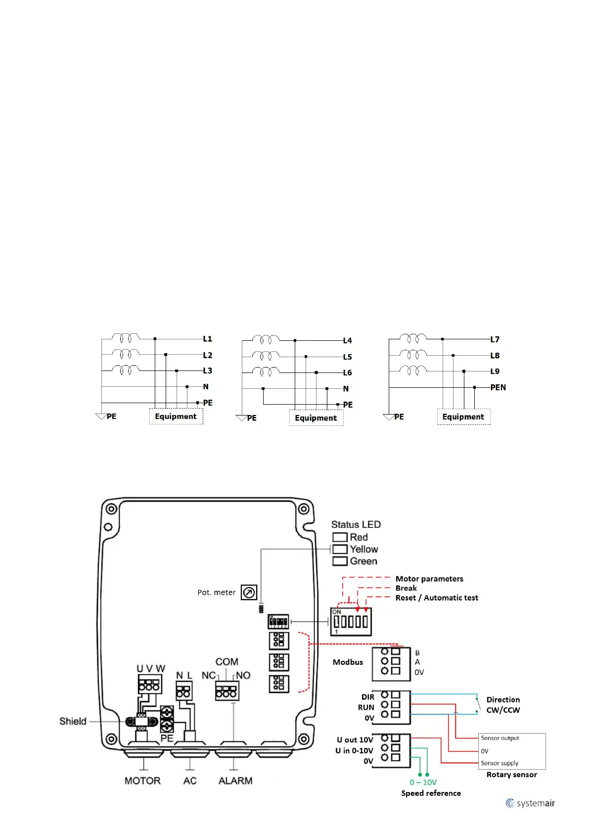
earthing systems. For a view over the allowed power supply systems refer to Figure 4.
Figure 4 – Power supply systems
TN – S TN – C – S TN – C
5.2.2 Overview of general electrical connections
A general diagram on how to connect NOVA RHC is depicted below. Detailed instructions are given below, in steps.