10
| Installation
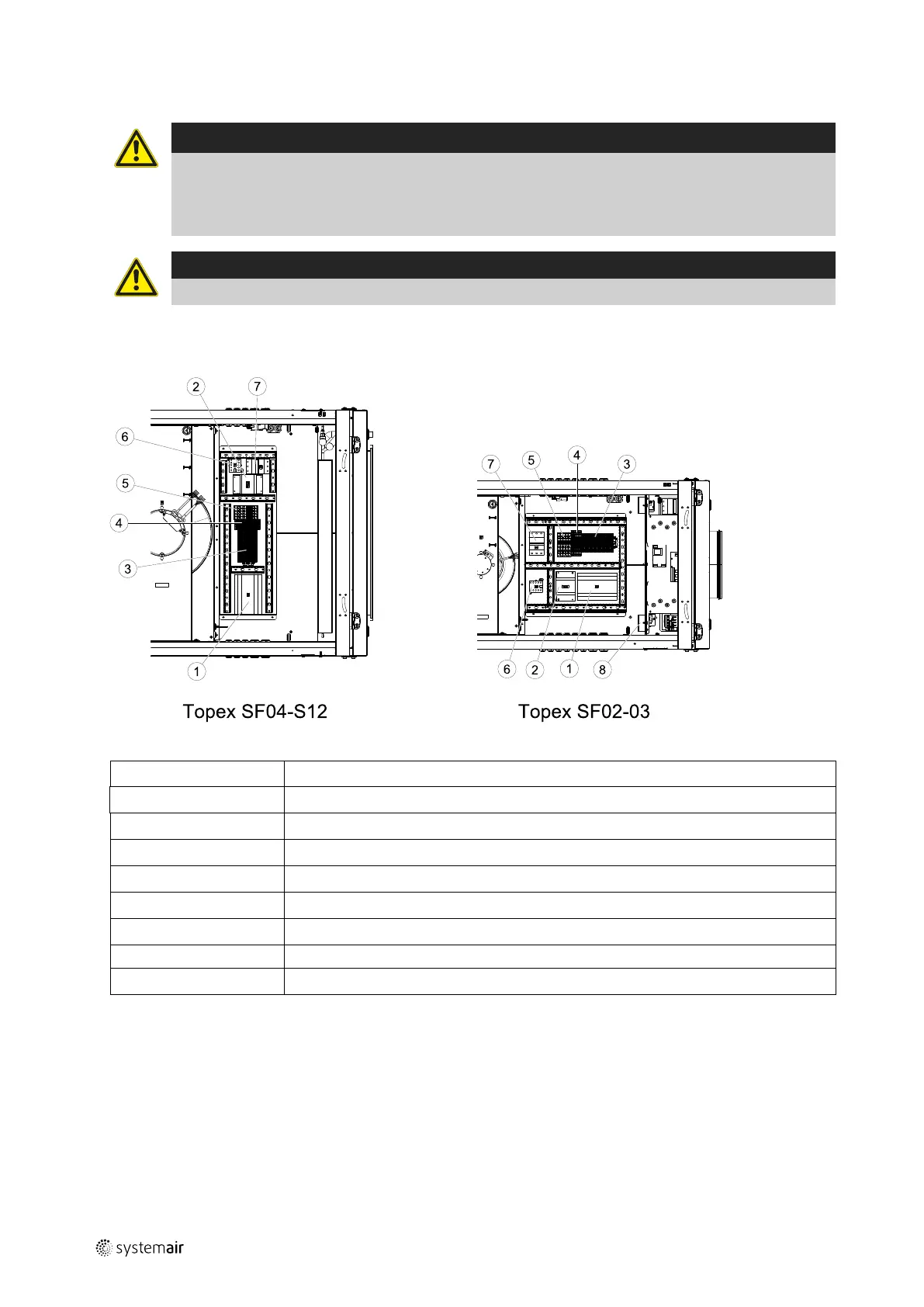
4.4.2 Electrical connection box, components
Danger
• Make sure that the mains power supply to the unit is disconnected before performing any maintenance
or electrical work!
• All electrical connections must be carried out by an authorized installer and in accordance with local rules
and regulations.
Caution
Be careful so the hatch doesn’t fall down if the unit is false ceiling mounted.
Topvex SF is equipped with a built in regulator and internal wiring.
Loosen the 4 screws to remove the hatch to the electrical connection box.
Fig. 6 Connection box
Position Description
1
Regulator E283 WEB
2
Transformer 230/24V AC
3
Terminals for internal and external components
4
Terminals for internal wiring
5
Terminals for mains power supply to the unit
6
Contactor (K2) On/Off Pump control water (HW units only, not present in EL-units)
7
Automatic fuse
8
Reset for overheat protection (only EL units)
130324 | A004
 Loading...