7
Anlegget er beregnet for kontinuerlig drift,
og skal bare stoppes for vedlikehold/
service.
Aggregatet är anpassat för kontinuerlig drift,
och ska bara stoppas vid service/ skötsel.
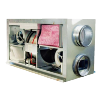
BEDIENUNG (Fig. 3)
Die Anlage wird über eine integrierte
Bedieneinheit mit folgenden Funktionen
betrieben:
Luftvolumenstrom (Ventilatordrehzahl)
Schalter für die Wahl von 3 Stufen (2).
Min Minimaler Luftwechsel. Einzustellen
während des Urlaubes oder wenn
sich niemand im Gebäude aufhält.
Norm Normalbetrieb, angepasst an die
Gebäudegröße. Luftvolumen kann in
3 Stufen gewählt werden (130, 160
und 180V), siehe Montageanleitung.
Max Max. Luftwechsel. Einzustellen, wenn
einerhöhter Luftwechsel nötig ist.
Zulufttemperatur (1)
Die Zulufttemperatur kann stufenlos über einen
Poti (1) an der Front eingestellt werden. Wenn
die Wärmerückgewinnung nicht ausreicht, um
die eingestellte Temperatur zu erreichen,
schaltet sich automatisch ein elektr. Heizregi-
ster zu, bis die Temperatur erreicht ist.
Innerhalb des markierten Bereiches kann die
Temperatur zwischen 15 und 25°C eingestellt
werden.
(Um eine möglichst hohe Energieausbeute zu
erzielen, sollte die Temperatur so niedrig als
möglich eingestellt sein. Dabei sollten
Zugerscheinungen ausgeschlossen sein.)
Enteisung
In extrem kalten Zeiten kann es zu Eisbildung
im Wärmetauscher kommen. Ein Frostschutz-
thermostat stoppt den Zuluftventilator und der
Tauscher wird durch die warme Abluft enteist.
”Sommerbetrieb”
Wenn keine Wärmerückgewinnung erforderlich
ist, kann der Tauscher durch einen Sommer-
block ersetzt werden. Dadurch wird der
Volumenstrom erhöht und man erfährt einen
kühlenden Effekt.
Die Anlage sollte kontinuirlich arbeiten und
nur zur Wartung und Reinigung
ausgeschalten werden.
OPERATION (Fig. 3)
The unit is equipped with an integrated
control panel with the following functions:
Airflow (Fan speed)
Switches for choice of airflow in 3 steps (2).
Min Minimum ventilation. To be used during
holidays or when the building is not in
use.
Norm Normal ventilation adapted to the
building. Airflow for normal ventilation can
be chosen in 3 steps (130, 160 eller 180
V) (see installation instructions).
Max Forced ventilation. Is used when extra
airflow is required.
Supply air temperature (1)
Supply air temperature can be controlled
stepless within the comfort area from switch (1)
on the control panel. When heat recovery from
the extract air is insufficient to obtain set supply
air temperature, an electrical heater battery will
automatically be switched on, to ensure that
supply air temperature is according to setting
on thermostat. Normal setting within the marked
area will ensure a supply air temperature of 15 -
25
o
C from the unit.
(In general it is recommended to set supply air
temperature as low as possible, avoiding the
feeling of draught. This gives the ultimate
energy and ventilation efficiency).
Defrosting
In periods when outdoor temperature is low, ice
and rime may build up inside the exchanger
block. A defrost thermostat will stop the inlet fan
when required. The warm extract air will then
melt the ice/rime in the exchanger block.
"Summer operation"
The exchanger block can be replaced by a
summerblock when heat recovery is not
required. This will increase the airflow and give
a cooling effect on hot summer days.
The system should operate continuously,
and only be stopped for maintenance and
service.
 Loading...