Do you have a question about the SZKTDZ KT-LCD4 and is the answer not in the manual?
Provides detailed dimensions and physical characteristics of the meter.
Illustrates the electrical connections for the meter.
Step-by-step guide for mounting and connecting the meter.
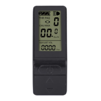
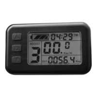
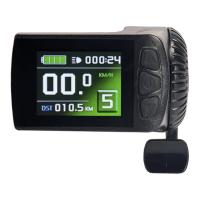
Lists and briefly describes all major functions of the KT-LCD4 meter.
Details all icons, indicators, and data shown on the meter display.
Explains the purpose and operation of each button on the meter.
Covers powering on/off and basic operational procedures.
Describes different screen layouts and transitions.
Shows how throttle engagement is indicated on the display.
How to select different levels of power assistance.
Explains the low-speed assist for pushing the bike.
How to activate and manage the cruise control feature.
Controls for meter backlighting and vehicle headlights.
Explains the visual indicator for brake lever activation.
Details how battery charge level is displayed.
Covers single data clearing and automatic prompt interface.
Explains how to read and interpret error codes.
How to set and adjust the maximum riding speed limit.
Setting the correct wheel diameter for accurate speed readings.
Configuring speed and mileage units (Km/h, MPH).
Procedure to exit the general project setting mode.
Setting motor characteristic parameter (gear ratio x magnet pieces).
Configuring wheel speed pulse signals for accurate speed measurement.
Setting the power assist control mode (torque or speed).
Configures the throttle startup mode (non-zero or zero startup).
Sets the power monitoring mode (real-time voltage or smart power).
Procedure to exit the P parameter setting environment.
Selects the power-assist sensor type and parameters.
Sets the motor phase classification coding for identification.
Initializes the power assist ratio gears upon startup.
Configures various throttle functions and speed limits.
Adjusts the controller's maximum operating current limit.
Adjusts the brightness level of the meter's backlight.
Enables or disables the cruise control function.
Sets whether to display the motor operating temperature.
Configures a password for meter startup.
Enables or disables automatic restoration of factory settings.
Selects meter attributes, including communication protocol compatibility.
Adjusts the minimum operating voltage for voltage shortage detection.
Sets ABS braking strength and energy recovery efficiency.
Tunes power-assist strength for intelligent pedal motor.
Procedure to exit all parameter setting environments.
Wiring diagram for the meter parameter copy function.
Details on the special wiring cable used for parameter copying.
Display interface indicating successful parameter copying.
| Display Type | LCD |
|---|---|
| Voltage | 24V/36V/48V |
| Communication Protocol | UART |
| Brightness Adjustment | Yes |
| Waterproof Level | IP65 |
| Compatibility | KT series controllers |
| Display Information | Speed, Battery Level, Error Codes |
| Functions | Error Diagnostics |