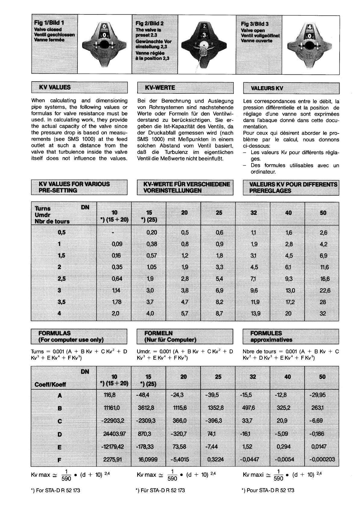
When calculating and dimensioning
pipe systems, the following values or
formulas for valve resistance must be
used. In calculating work, they provide
the actual capacity of the valve since
the pressure drop is based on measu-
rements (see SMS 1000) at the feed
outlet at such a distance from the
valve that
turbulente
inside the valve
itself does not influence the values.
Bei der Berechnung und Auslegung
von Rohrsystemen sind nachstehende
Werte oder Formeln fur den
Ventilwi-
derstand zu berucksichtigen. Sie er-
geben die Ist-Kapazitat des Ventils, da
der Druckabfall gemessen wird (nach
SMS 1000) mit MeBpunkten in einem
solchen Abstand vom Ventil basiert,
da8 die Turbulenz im eigentlichen
Ventil die MeBwerte nicht beeinfluBt.
Les correspondances entre le debit, la
pression differentielle et la position de
reglage d'une vanne sont exprimees
dans I'abaque donne dans cette
docu-
mentation.
Pour ceux qui desirent aborder le pro-
bleme par le calcul, nous donnons
ci-dessous:
-
Les valeurs Kv pour differents regla-
ges.
-
Des formules utilisables avec un
ordinateur.
Turns
=
0.001 (A
+
B Kv
+
C
Kv2
+
D Umdr.
=
0.001 (A
+
B
Kv
+
C
Kv2
+
D Nbre de tours
=
0.001 (A
+
B Kv
+
C
Kv3
+
E
Kv4
+
F Kv5) Kv3
+
E
Kv4
+
F Kv5) Kv2
+
D Kv3
f
E
Kv4
+
FKv5)