Do you have a question about the TACKLIFE PBS01A and is the answer not in the manual?
Covers the machine's access door and its locking mechanism.
Details safety features and guidance systems for the saw blade.
Explains the function and use of the longitudinal limit stop.
Covers table features, frame, underframe, on/off switch, and mitre gauge.
Handle for saw blade tensioning, belt tensioning, and sawblade guard adjustment.
Safety for work area, lighting, and environmental conditions.
Protecting oneself from electric shock, keeping children away, clothing, and PPE.
Connecting dust extraction and securing the workpiece during operation.
Avoiding awkward postures and maintaining tools for safe operation.
Procedures for power disconnection, avoiding inadvertent starts, and checking tool condition.
Risks from accessories, qualified repairs, and cable usage.
Specific safety rules for maintenance, cutting, and operation.
Safety measures for workpiece support, guards, blade usage, and transport.
Steps to follow in case of an accident or injury.
Securing the machine, checking covers, and listing assembly tools.
Guide for assembling the machine's base and frame.
Fitting and aligning the machine's work table.
Attaching width extension and installing/setting the parallel stop.
Setting the cutting width using the parallel stop.
Using the table extension for wider workpieces.
Procedures for replacing the saw blade and adjusting its alignment.
Adjusting the motor's revolutions per minute.
Adjusting sawblade guides and back pressure bearings.
Setting guide rollers and storing the push rod.
Using the transverse cutting gauge for angled cuts.
How to operate the machine's power switch.
General safety recommendations for operating the band saw.
Making straight cuts along the length of a workpiece.
Making cuts at an angle using the saw bench.
Cutting curves and radii with the band saw.
Making cuts across the workpiece using a gauge.
Routine cleaning and upkeep of the machine.
Details maintenance requirements for the equipment.
Notes on motor overload protection and general electrical safety.
Common causes and hazards of damaged electrical cables.
Guidelines for environmentally sound disposal of the equipment.
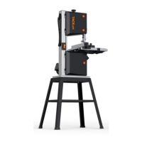
This document describes a bandsaw, model PBS01A, designed for performing longitudinal and cross cuts on timber or wood-type materials. It is important to note that for cutting round materials, suitable holding devices must be used. The machine is intended for its prescribed purpose, and any other use is considered misuse, with the user/operator being liable for any resulting damage or injuries. The bandsaw must only be operated with suitable saw blades, and users should adhere to all safety regulations, assembly instructions, and operating instructions provided in this manual.
The bandsaw is equipped with a motor that operates at 220-240V~, 50Hz. It features a saw band that can be adjusted for tension and speed, allowing for versatile cutting applications. The saw blade guidance system ensures precise cuts, and a sawblade guard is adjustable to accommodate different workpiece heights. The machine includes a tabletop with a width enlargement feature, a longitudinal limit stop, and a mitre gauge for various cutting angles and dimensions.
Before operation, the machine must be securely bolted to a workbench or solid base using the provided holes in the machine foot. The saw table needs to be correctly mounted, and all covers and safety devices must be properly fitted before switching on the machine. It's crucial to ensure the blade runs freely without touching the table. When working with wood that has been processed before, users should check for foreign bodies like nails or screws.
The base assembly involves attaching stand feet, stand braces (below and above) using screws, washers, and nuts. The assembled frame is then secured to the base plate of the bandsaw. All screws and nuts should be hand-tightened initially and then firmly tightened once the machine is on a level surface.
The table insert is placed in its designated recess on the work table. The band saw blade is threaded through the slot on the machine table, which is then placed on the table guide and secured with a fitting screw, quick release lever, and washer. The table can be adjusted to a right-angle using an adjustment screw, and the scale pointer should be set to 0.
The table width enlargement is attached by removing two bolts and washers, sliding the enlargement onto the table, and ensuring the clamping lever is open. It should be pushed fully onto the table, and the bolts re-fitted to limit its extension. This feature is particularly useful for wide workpieces.
The parallel stop is positioned at the back and fixed by clamping it downwards. It can be removed by pulling the clamping lever upwards. The clamping force of the parallel stop can be adjusted using a knurled nut at the rear.
The parallel stop is essential for cutting sections of wood lengthways. It can be placed on the guide rail to the left or right of the sawing blade. Two scales on the guide rail indicate the distance between the stop rail and the sawing blade, allowing for precise width adjustments.
For particularly wide workpieces, the table width enlargement should always be used. The clamping lever is loosened, and the enlargement is pulled out sufficiently to support the workpiece without tipping.
Before changing the saw blade, the mains plug must be pulled, and protective gloves should be worn to prevent injury. The parallel stop and table width enlargement are removed, and the saw band guard (top and bottom) is opened. The saw band tension is relieved using the clamping screw, and the old band is removed before inserting a new one.
The saw blade should run in the center of the band wheels. The upper band wheel is turned by hand in the cutting direction, and side correction is made using the handle. After multiple turns, the saw band should run over the center of the band wheel. The final tension is determined by turning the band wheel by hand and adjusting the tension screw. Wider saw blades require more tension. After successful setting, the locknut is firmly tightened, and the guard is closed. Over-tensioning can cause premature breaking. After work, the tension bolt should be released to relieve tension.
To adjust the speed, the mains plug must be pulled, the lower guard opened, and the table top tilted slightly. The belt is released with the tension handle and moved to the desired position (S1 or S2). The belt is then re-tensioned, and the lower guard is closed. Rpm stage 1 (360 m/min) is for hardwood and fine cuts, while Rpm stage 2 (720 m/min) is for softwood and less fine cuts.
The sawblade guiding is adjusted with a fixing button. The upper sawblade guiding can be set from 0 to 175 mm workpiece height. A small clearance to the workpiece ensures optimum guiding and safe working.
The back pressure bearings accept the feed pressure of the workpiece. They should be set so that they slightly touch the sawblade back, with a distance of 0.5 mm. The screws are then tightened.
The upper guide rollers are set to the corresponding sawblade width. Their front edges must not exceed the tooth base of the sawblade. When they slightly touch the sawblade, the screws are tightened.
Similarly, the lower guide rollers are set to the corresponding sawblade width. Their front edges must not exceed the tooth base of the sawblade. When they slightly touch the sawblade, the screws are tightened. The sawblade must not jam.
The push rod should always be within reach and stored on the hook provided on the top left side of the band saw.
The lateral stop of the transverse cutting gauge is slid into a groove in the saw bench. The grip screw is released, and the lateral stop is turned to the desired angular dimension. The grip screw is then retightened. The stop rail can be slid against the lateral stop by loosening the knurled screws and sliding it into position, then retightening the screws. It is important not to slide the stop rail too far towards the saw blade.
To turn the machine on, press the green button. To turn it off, press the red button. The band saw has an undervoltage switch, meaning it must be switched back on after a power failure. All protective devices and guards must be fitted when working, and the machine will only start with the cover closed.
When lifting the machine, pay attention to its weight and seek assistance. Use transport equipment. The machine can be moved by standing on the side of the wheels, pulling the upper part towards you so it stands on two wheels, and holding it by its frame. Be aware of the machine's high center of gravity. Never use safety guards to lift or transport the unit.
When working in closed rooms, connect the machine to a suction unit. Loosen the sawband when the machine is not in operation and attach a notice for the next user. Store unused sawbands safely in a dry place and check for faults before use. Wear suitable gloves when handling sawbands. Ensure all protective devices are securely mounted. Never clean the sawband or guide with a hand-held brush while running. Wear protective glasses, hearing protection, and a hairnet if you have long hair. Position the sawband guide as close as possible to the workpiece and ensure sufficient lighting. Always use the fence for straight cuts. Use a push stick for narrow workpieces and for diagonal cuts. Ensure safe workpiece guidance for arced and irregular cuts, pushing the workpiece evenly with both hands. Use a pattern for repeated cuts. Ensure the workpiece does not roll when cutting round pieces. Use the special transverse cutting gauge for safe transverse cutting.
Position the longitudinal fence on the left side of the saw band according to the desired width. Lower the saw band guide onto the workpiece and switch on the saw. Press one edge of the workpiece against the longitudinal fence with the right hand, with the flat side on the saw bench. Slide the workpiece at an even feed rate into the saw band. Long workpieces must be secured against tipping at the end of the cut. For narrower workpieces, a push stick is essential.
To make angled cuts parallel to the saw band, tilt the saw bench forwards from 0° to 45°. Release the locking handle, set the desired angle on the degree scale, and retighten the handle. With a tilted saw bench, the longitudinal fence must be positioned on the downward-facing side to the right of the saw band to secure the workpiece against slipping.
For curves and radii, lower the saw band guide onto the workpiece and switch on the saw. Press the workpiece firmly onto the saw bench and slowly slide into the saw band. Use a low advancing speed for freehand cutting. For tight curves, auxiliary cuts may be helpful.
Set the transverse cutting gauge to the desired angle and perform the cut as described for longitudinal cuts.
Before any adjustment, maintenance, or service work, disconnect the mains power plug. Regularly wipe chips and dust off the machine with a cloth. Oil rotary parts monthly, but do not oil the motor. When cleaning plastic parts, do not use corrosive products.
Keep all safety devices, air vents, and the motor housing free of dirt and dust. Wipe the equipment with a clean cloth or blow it with compressed air at low pressure. Clean the device immediately after use with a moist cloth and soft soap, avoiding cleaning agents or solvents that could damage plastic parts. Ensure no water seeps into the device to prevent electric shock.
Store the device and its accessories in a dark, dry, and frost-proof place inaccessible to children, with an optimum temperature between 5°C and 30°C. Cover the electrical tool to protect it from dust and moisture, and store the operating manual with the tool.
The installed electric motor is connected and ready to work, complying with VDE and DIN regulations. The customer-side mains supply and extension line must meet these regulations. In case of motor overload, it will switch off and can be switched back on after a cool-down period.
Regularly check electrical connection lines for damage such as drag marks, kinks, cuts, or insulation damage from pulling the plug or aging. Defective lines are hazardous and must not be used. Only use connection lines labeled H05VV-F.
The manual provides a troubleshooting guide for common issues like the motor not working, excessive noise, overheating, rough cuts, workpiece pulling away, saw blade running crooked, burn marks, or saw blade jamming. Solutions typically involve checking fuses, inspecting the motor, ensuring proper saw blade tension and guidance, cleaning the saw blade, or replacing defective parts.
| Power Source | Corded Electric |
|---|---|
| Voltage | 120V |
| Frequency | 60Hz |
| No-load Speed | 0-3000 RPM |
| Bevel Capacity | 45° |