the suction and discharge lines.
3. Position vertical and horizontal piping so bolt-holes on
p
ump and companion flanges match. Do not force the
suction and discharge lines into position. This may cre-
a
te excess stress on the pump casing and flanges.
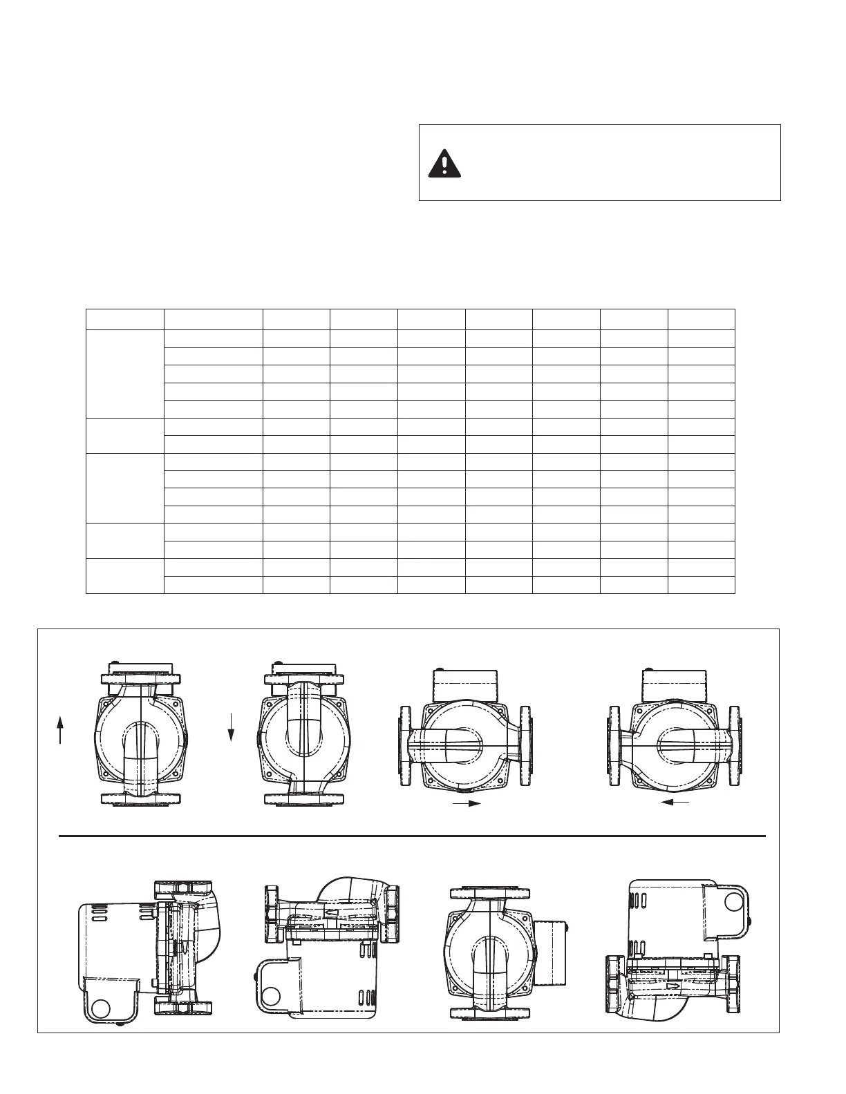
B. Mounting Position:
• Always install pump with the motor shaft in the horizon-
t
al position and the capacitor/conduit box oriented on
top of the motor housing, as shown in Fig. 1.
• Standard pump body mounting position is with the flow
in the up-discharge direction (body position #3). The
pump body may be field-rotated in any direction to
accommodate system piping and flow direction.
• Be sure to align the arrow on the casing with desired
FLOW
NOT RECOMMENDED
RECOMMENDED
FLOW
FLOW
FLOW
CAUTION: Do not support, suspend or brace
pump motor or early failure may result.
Support provided by casing is sufficient for
s
tructural integrity of pump
Fig. 1 – Installation Positions
Models Connection
3
⁄4" 1" 1
1
⁄4" 1
1
⁄2" 2" 2
1
⁄2" 3"
2
400-10-3P
2400-20-3P
2
400-45-3P
2
400-50-3P
Iron NPT 110-251F 110-252F 110-253F 110-254F — — —
Stainless Steel NPT 110-251SF 110-252SF 110-253SF 110-254SF — — —
Bronze Sweat 110-523BSF 110-524BSF 110-525BSF 110-526BSF — — —
S
hut-Off NPT
S
F-075T
S
F-100T
S
F-125T
S
F-150T
—
—
—
S
hut-Off Sweat
S
F-075S
S
F-100S
S
F-125S
S
F-150S
—
—
—
2
400-50/2-3P
2
", 2 Bolt
I
ron NPT
—
—
—
—
1
94-2124F
—
—
Stainless Steel NPT — — — — 194-2124SF — —
2400-30-3P
2400-40-3P
I
ron NPT
—
—
1
94-1540F
1
94-1542F
—
—
—
Stainless Steel NPT — — 194-1540SF 194-1542SF — — —
Shut-Off NPT — — SF-125T-0012 SF-150T-0012 — — —
Shut-Off Sweat — — SF-125S-0012 SF-150S-0012 — — —
2400-60-3P
2400-65-3P
2400-70-3P
Iron NPT — — — — 185-086C — —
Bronze NPT — — — — 185-086B — —
2400-70/3-3P
3", 4 Bolt
Iron NPT — — — — — 185-112C 185-113C
Bronze NPT — — — — — 185-112B 185-113B
Table 1 – 2400 SERIES COMPANION FLANGE SETS
 Loading...