2
B.1 Motor Rotation Procedure
Caution: Motor is heavG=
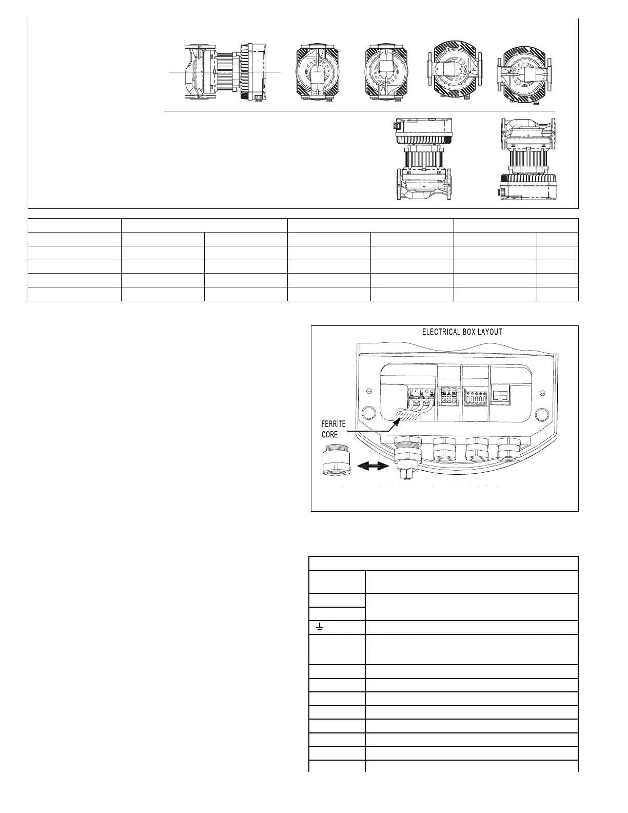
1. If possiVle5 change the orientation of the motor Vefore
installing pump in piping. With motor in a vertical position,
remove the 4 bolts (
5
⁄16” or 8mm hex wrench required) and turn
the motor to agree with desired orientation of pump (see
Figure 1). If motor won’t turn, insert a screwdriver between
pump casing and motor flange and raise slightly. Try turning
motor. Insert screwdriver on opposite side, raise slightly, and
try turning the motor. Motor should now turn - now line up bolt
holes when desired orientation is achieved.
2. Caution: If system is filled and pressurized, shut off valve
before and after the Viridian. Allow to cool if system fluid is hot.
3. If the pump is already installed in the piping, remove the 4
bolts (
5
⁄16” or 8mm hex wrench required) and try rotating the
motor without backing it out from the pump casing. Try crack-
ing the motor approximately .020” using a screwdriver
between the motor and pump housing and try turning the
motor.
4. If motor will not move, remove motor completely.
5. Remove impeller, rotor, and rotor can from the motor. Note:
Rotor and impeller assembly will come out first. Remove rotor
can from motor and put aside.
6. Install impeller and rotor assembly into pump.
7. While holding rotor, install O-ring in casing, and then slide rotor
can over rotor and slide all the way in.
8. Rotor and rotor can should stay in place while you pick up the
motor. If they do not, start over to assure O-ring is properly
located and have someone hold the assembly in place with a
screwdriver on top of the plate.
9. Pick up the motor with the terminals properly orientated and
carefully start to slide the motor over the rotor can. The resis-
tance of the sliding will keep the rotor and rotor can assembly
in place and the screwdriver can be moved. Note: Do not
alloW the motor to droop or the OYring might get out of
position.
10. Line up the bolt holes, reinstall the bolts, and tighten in a
cross-pattern.
11. Carefully open shut off valves and check for leaks.
Make sure that the electrical box cover is mounted and that all
cable glands are installed to prevent dust and particles from cont-
aminating the electrical box.
B.- Electrical Connections:
NOTE: For 200 to 240/1/60 volt, L1 and L2 are connected to L and
N in the electrical box.
CONNECTION FUNCTIONS
TERMINAL
MAR&INbS
DESCRIPTION
L
Electrical power supply. See pump ratings for
applicable supply ranges.
N
Ground connection
FERRITE
CORE
Ferrite core for HF interference compliance. Ground,
L and N wires should pass through it.
(Part packaged separately.)
NC Normally closed relay connection
C Common relay connection
NO Normally open relay connection
IO2 Digital input 2
24V +24 Vdc @ 100mA max output
GND (0V) 24 Vdc ground
IO1 Digital input 1
ETHERNET Ethernet connection
 Loading...