Do you have a question about the Taco Zone Sentry Series and is the answer not in the manual?
Instructions for mounting the valve body and checking clearance requirements before installation.
Guidelines for soldering, including temperature, flame direction, and cooling the valve body.
Instructions for attaching the valve operator in either direction, with reference to Figure A.
Steps to remove the valve operator by releasing a clip, with reference to Figure C.
Procedure to re-assemble the operator, aligning the stem and securing with the release clip.
Procedure for initial field installation, capacitor charging, and the indicator light.
Describes how the valve operator responds to thermostat signals and power status.
Caution against using zone valves with indirect water heaters without a tempering device.
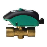
The Taco Zone Sentry Zone Valve is a sophisticated control device designed for use in both open and closed hot or chilled water systems. It provides on-off, normally open, or normally closed control for a wide range of heating and cooling applications, including fan coils, radiators, convectors, air handlers, heat pumps, and radiant systems. Its design emphasizes ease of installation and operation, making it a versatile choice for various HVAC setups.
One of the key features of the Zone Sentry valve is its flexible installation. The valve body can be installed in any position or orientation, which is particularly beneficial for installations in confined spaces. Furthermore, the operator can be mounted to the valve body in either direction, offering additional flexibility for tight baseboard jobs or other challenging installations. This adaptability simplifies the planning and execution of plumbing work.
The valve incorporates snap-in quick connects on the back, ensuring a simple, secure, and fast wiring hook-up. This design minimizes the time and effort required for electrical connections, contributing to a more efficient installation process. A green LED light provides visual feedback on the valve's functionality and thermostat status, allowing for quick and easy monitoring of its operation.
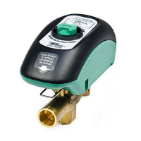
For situations where power is unavailable, the Zone Sentry valve includes a manual override button located on the top of the valve. This button allows the ball valve to be rotated up to 90 degrees, and a slot indicates the current position of the valve. This manual override is a crucial feature for maintenance or in emergency situations, ensuring that the system can still be controlled even without electrical power.
When it comes to installation, specific procedures must be followed to ensure proper function and longevity. Before soldering, the operator must be removed from the valve body. The ball valve itself must be in the full open position during soldering. The manufacturer recommends using solder with a melting point below 600°F and advises against overheating the valve. Directing the flame tip away from the center of the valve and quickly cooling it with a wet rag are also important steps. Solder build-up on the ball valve can impede its proper opening and closing, so rotating the manual operation button several times after soldering can help loosen any potential build-up. The valve body can be submerged for leak testing before the operator is attached, which is a valuable step for ensuring system integrity.
Re-assembling the operator to the valve body involves aligning the "D" shaped valve stem with the corresponding "D" shaped operator drive cavity. The "D" shaped stem design ensures correct insertion every time. The operator is then slid onto the valve stem, and a release clip at the front of the operator is pushed in and held until the operator slips over the valve locking posts. Once the operator is flush with the valve body, the release clip can be released. The manual emphasizes that very little force should be required to remove the operator without the release clip if it is properly assembled, and if it slides up the stem, the assembly process should be repeated.
Wiring the operator must be done in accordance with system requirements and applicable electrical codes. The plug-in quick connects can be disconnected from the valve operator to facilitate wiring. Wires are inserted into the quick connects and tightened by turning a screw. A critical caution is provided against jumpering power/motor (24 VAC) connection terminals, even temporarily, as this can damage the thermostat's heat anticipator.
The operational mode of the Zone Sentry valve involves a brief charging period upon initial field installation. The capacitor requires up to 20 seconds to fully charge before the valve begins to turn, with charging time varying during normal operation. During this charging phase, the green LED light will flash. Once charged, the LED will stop flashing and remain ON, indicating that the valve's operator is rotating the ball valve. The green LED stays ON as long as the thermostat is calling for heat or cool (i.e., the unit is powered). When the thermostat is satisfied, the green LED turns OFF, and the valve rotates 90 degrees to its normal or non-powered position. For a normally closed (NC) version, the operator opens the valve when the thermostat calls and rotates it to the closed position when the thermostat is satisfied.
The manual also provides specific wiring diagrams for replacing various existing zone valves, including Honeywell, Erie, Sparco, Flair, Taco 3-Wire, Taco 570 Series, and White-Rodgers valves, ensuring compatibility and ease of integration into diverse systems. A general warning is issued against using zone valves on indirect water heaters without a tempering device, highlighting a crucial safety consideration.
In summary, the Taco Zone Sentry Zone Valve is designed for reliable, flexible, and user-friendly control in hydronic systems. Its robust construction, adaptable installation options, clear operational indicators, and manual override capabilities make it a practical solution for a wide range of heating and cooling applications, while detailed installation and wiring instructions ensure proper setup and long-term performance.
| Voltage | 24 VAC |
|---|---|
| Type | Zone Valve Control |
| Input Voltage | 24 VAC |
| Output Voltage | 24 VAC |
| Operating Temperature Range | 32°F to 104°F (0°C to 40°C) |
| Enclosure Rating | NEMA 1 |