TM8100/TM8200 Service Manual Installing a Remote Kit 513
© Tait Electronics Limited June 2006
25.1.3 Removing the Control Head from the Radio Body (if necessary)
Caution During this procedure, take care that the control-
head seal is not damaged. Damage to this seal
reduces environmental protection.
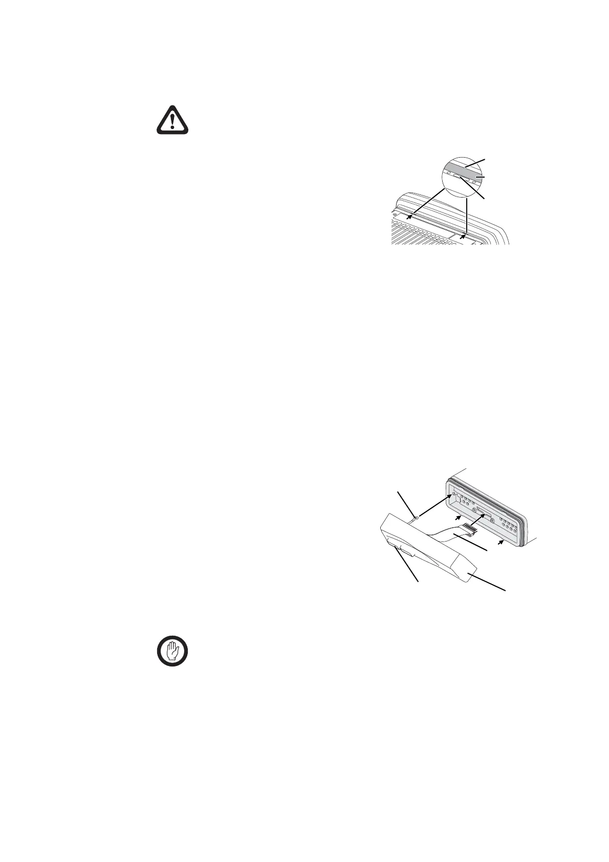
1. On the underside of the radio,
insert a 5mm (3/16 inch) flat-
bladed screwdriver between the
control head and the control-head
seal, in the positions shown.
Insertion points and are lever
points and are indicated on the
radio chassis by a dot-dash-dot pattern (
•
–
•
).
2. Use the screwdriver to lift the control head off the chassis clip, then
repeat in the other position.
3. Unplug the control-head loom from the radio body.
The control head is now separate from the radio body.
25.1.4 Installing the Torso Interface
The torso interface must be installed onto the radio body, in place of the
control head.
1. Screw the solder tag
1)
onto one of the screw bosses on the
radio chassis.
2. Plug the torso-interface loom
j
onto the control-head connector.
3. Insert the bottom edge of the
torso interface
b
onto the two
clips in the front of the radio
chassis, then snap into place.
4. Remove the bung
h
covering
the outer RJ45 connector. The
remote cable
e
will plug into this
connector once the installation is complete.
Important The inner RJ45 cavity is not used and has no connector
installed so the RJ45-cavity bung must be installed at
all times.
This ensures that the torso interface is sealed against water,
dust and other environmental hazards.
lever point
control-head seal
indication of
lever point
j
1)
b
h
 Loading...


