Do you have a question about the Tait TM8200 mobiles and is the answer not in the manual?
Defines the scope of the service manual for level-1 and level-2 repairs of TM8100/TM8200 radios.
Lists hardware and software versions with corresponding internal part numbers (IPNs) for boards.
Lists related documentation available for the product, categorized by manuals and PCB information.
Details the issue number, publication date, and description of changes for each manual revision.
Explains the different types of alerts used in the manual: Warning, Caution, Important, and Note.
Provides an alphabetical list of abbreviations used in the manual with their meanings.
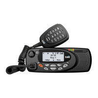
Introduces the TM8100/TM8200 series radios, their applications, and describes frequency bands, RF output power, accessories, and product codes.
Describes the mechanical design, architecture, operation modes, and pinouts of radio connectors.
Describes and illustrates the circuitry of the main board and control-head boards, covering transmitter, receiver, synthesizer, CODEC, power supply, interface, and digital boards.
Covers techniques and processes for servicing the radio, including repair levels, tools, precautions, test equipment setup, and website access.
Provides instructions on how to remove, disassemble, and reassemble the control head and radio body.
Outlines the full sequence of tasks for servicing a radio, including initial inspection, repair, final inspection, and administration.
Guides the diagnosis of faults in the power supply circuitry, covering SMPS, regulators, and power-up configurations.
Covers diagnosis of faults involving signals output from or input to the radio's internal circuitry via various connectors.
Guides the diagnosis of faults in the frequency synthesizer, including initial checks, RF PLL, and FCL circuitry.
Details the operation, configuration, installation, programming, interface specification, circuit description, and PCB information for the Line-Interface Board.
Describes the operation, installation, interface specification, and PCB information for the RS-232 board, providing external device connectivity.
Explains how to change options extender links, install the board, its interface specification, and PCB information.
Covers the operation, installation, adjustment, radio programming, interface specification, and circuit description of the DTMF microphone.
Details the installation, radio programming, and interface specification for the concealed and dynamic microphone support kit.
Describes the installation, radio programming, and interface specification for the concealed microphone kit.
Covers the installation, radio programming, and interface specification for the keypad microphone.
Explains the installation, removal, replacement, and disassembly of the security bracket.
Guides the installation of remote control-head kits, including overview, parts, installation steps, circuit description, and PCB information.
Provides instructions for installing the enhanced remote kit, covering overview, parts, installation steps, circuit description, and PCB information.
Details the interface specification and PCB information for the control head interface box.
Covers the interface specification and PCB information for the extender box.
Explains the installation, radio programming, operational testing, and interface specification for the crossband linking cable.
Details the hardware configuration, installation, and radio programming for the ignition sense kit.
Covers cross-band repeater operation, installation, radio programming, operational testing, and interface specification for the linking cable.
Describes the operation, installation, adjustment, radio programming, and interface specification of the desktop microphone.
Covers the installation, radio programming, and interface specification for the handset.
Details the installation of high-power remote speakers, including mounting and power connector wiring.
Explains VOX operation, installation, radio programming, interface specification, and circuit description for the remote PTT and hands-free kits.
Covers the operation, installation, adjustment, radio programming, and interface specification of the desktop microphone.
Details the operation, installation, adjustment, radio programming, and interface specification for the desktop microphone.
Describes the TOPA-SV-024 test unit, its test equipment setup, operation, and PCB layout.
| Number of Channels | 128 |
|---|---|
| IP Rating | IP54 |
| Channel Spacing | 12.5 kHz |
| Operating Temperature | -30°C to +60°C |
| Signalling | DTMF, MDC1200 |