524 TMAA02-08 Keypad Microphone TM8100/TM8200 Service Manual
© Tait Electronics Limited November 2007
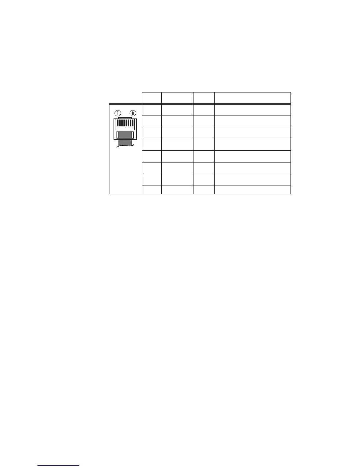
23.3 Interface Specification
The following table and diagram summarizes the signals used for the keypad
microphone on the radio’s microphone connector and shows the interface
between the keypad microphone and the radio.
Table 23.1 Keypad microphone connector—pins and signals
Pin Signal Colour Description
1 RX audio — not connected
2 13.8V black power supply
3 TXD green transmit serial data
4 PTT white PTT and hookswitch
5 MIC blue audio from the microphone
6 GND red ground
7 RXD yellow receive serial data
8 IO — not connected
 Loading...


