EasyManua.ls Logo

taiyo RX-802AS User Manual

taiyo RX-802AS
32 pages
To Next Page IconTo Next Page
Page #1 background imageLoading...
Page #1 background image
PB
1
TAIYO ELECTRIC IND.CO.,LTD.
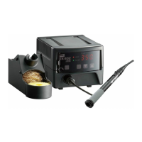
TEMPERATURE CONTROLLED
LEAD-FREE SOLDERING STATION
RX-802AS
Thank you for buying a goot soldering station. Your new soldering station has been
engineered and manufactured to the goot high standards for dependability, ease of
operation, and operator safety. If you follow the instructions and safety precautions in this
manual and use the soldering station properly and only for what it is intended, you will enjoy
years of safe, reliable service. Thank you again for buying a goot soldering station.
WARNING
Before using the soldering station, read the Operation Manual.
Failure to follow the safety precautions and instructions in this
manual could result in serious injury and property damage.
KEEP THIS MANUAL FOR FUTURE REFERENCE
TAIYO ELECTRIC IND.CO.,LTD.
OPERATION MANUAL
ver.
4
Tips not included
Tips sold separately
Questions and Answers:

taiyo RX-802AS Specifications

General IconGeneral
Brandtaiyo
ModelRX-802AS
CategorySoldering Gun
LanguageEnglish

Summary

OPERATION MANUAL ver. 4

RX-802AS Soldering Station Identification

Identifies the product model and type of soldering station.

Initial Safety Warning

Warns users to read the manual for safety and to prevent injury or damage.

Safety Mark Definitions

WARNING Symbol Definition

Defines the WARNING symbol and its associated risks.

CAUTION Symbol Definition

Defines the CAUTION symbol and its associated risks.

Specifications

Electrical and Performance Specs

Lists voltage, power consumption, temperature range, leak voltage, and ground resistance.

Physical Dimensions and Accessories

Details dimensions, weight, cord lengths, and included accessories.

Introduction

Unpacking and Package Contents

Guides users on checking the package contents and storing it for future use.

Name of Parts

Control Unit Components

Identifies parts of the control unit like the operation panel and connectors.

Soldering Iron Components

Identifies parts of the soldering iron, including tip, lever, and grip.

Tip Attachment Caution

Warns that tip calibration is required after attaching a new tip.

Operation Panel Details

Indicator Lamps

Explains the HEAT, SLEEP, ALARM, and KEY LOCK indicator lamps.

Control Keys Functions

Describes the function of the KEY LOCK, SETTING, DOWN, and UP keys.

Soldering Iron Stand ST-21 Instructions

Stand Safety Precautions

Provides warnings and cautions for safe use of the soldering iron stand.

Tip Cleaning Procedure with Stand

Details the method for cleaning the soldering tip using the stand's sponge and brass wool.

Rules for Safe Operation

General Safety Precautions

Covers environment, bystanders, proper use, apparel, and power supply connections.

Power Cord and Stand Safety

Details safe power cord handling and the importance of using the provided stand.

Additional Safety Guidelines

Tip Cooling and Cord Damage Protocols

Advises on proper tip cooling after use and procedures for damaged power cords.

Changing the Set Temperature

Temperature Adjustment Procedure

Details the steps to change the soldering station's set temperature.

Temperature Setting Timeout Note

Notes that inactivity during setting records the current display.

Tip Calibration

Setting the Tip Number (Tip No.)

Guides on how to input the correct tip number for calibration.

Tip Number Reference List

Provides a list of tip models and their corresponding tip numbers for reference.

Calibration Function

Calibrating the Tip Temperature

Outlines the procedure to calibrate the actual tip temperature against the set value.

Default Calibration Setting

States the default calibration value and procedure for changing tip numbers.

Sleep Function

Activating and Exiting Sleep Mode

Explains how to manually activate sleep mode and exit it using the sponge.

Automatic Sleep Mode Behavior

Describes how the station enters sleep mode automatically and reverts upon use.

Setting the Sleep Timer (CT)

Adjusting Sleep Start Time

Details the steps to change the sleep start time (CT) in minutes.

Disabling Sleep Function

Explains how to turn off the sleep function by setting the timer to 0.00.

Setting Sleep Sensitivity (DIF)

Adjusting Sleep Sensitivity Value

Guides on setting the sleep sensitivity (DIF) value in degrees Celsius.

Sensitivity Adjustment Notes

Provides notes on how DIF affects sleep function activation and stabilization.

Shutdown Function Settings

Setting the Shutdown Start Time (SUT)

Details the procedure to set the automatic shutdown start time in minutes.

Disabling Shutdown Function

Explains how to turn off the shutdown function by setting SUT to 0.

Soldering Time Alarm

Setting the Soldering Time Limit

Guides on setting the alarm for exceeding a specific soldering time.

Alarm Operation and Disablement

Explains how the alarm sounds and how to turn it off.

Temperature Range Alarms

Setting Upper and Lower Temperature Limits

Details how to set the upper (H) and lower (L) temperature limits for alarms.

Default Alarm Limit Settings

States the default upper and lower alarm limits set before shipping.

Alarm Sound Settings

Enabling and Muting the Alarm

Guides on switching the alarm sound ON or OFF.

Temperature Display Settings

Switching Between Celsius and Fahrenheit

Explains how to change the temperature display format between °C and °F.

Key Lock Function

Setting and Releasing the Code Number

Details the procedure to set or release the key lock using a code number.

Changing the Key Lock Code Number

Procedure for Changing Code

Outlines the steps to change the existing key lock code number.

Resetting the Key Lock Code

Procedure for Resetting Code Number

Provides the steps to reset the key lock code number, noting the use of '471'.

Restoring Default Settings

Procedure for Factory Reset

Explains how to restore all parameters to their factory default settings, including unlocking key lock.

Maintenance and Tip Replacement

Tip Replacement Safety Precautions

Warns that the tip is very hot and must be handled with care during replacement.

Tip Replacement Procedure

Details the step-by-step process for removing and installing a new soldering tip.

Tip Number Input Reminder

Advises inputting the correct Tip No. when changing tip types.

Soldering Iron Care and Maintenance

Grip Rubber and Housing Care

Details grip rubber replacement and housing cleaning guidelines.

Lead-Free Tip Care and Stand Use

Recommends temperature settings, tip care, and stand usage for lead-free soldering.

Troubleshooting

Tip Blackening and Wettability Issues

Offers solutions for blackened or non-wettable soldering tips.

Cleaning Sponge Maintenance

Provides guidance on cleaning or replacing the cleaning sponge.

Power On and Heating Faults

Lists checks for unit not powering on or tip not heating.

Replacement Tips

Replacement Parts

Grip Rubber Color Options

Details the available colors and part numbers for grip rubbers.

Parameter Reference