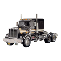
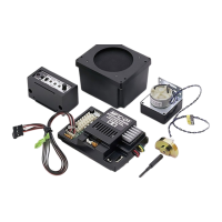
Do you have a question about the Tamiya 56323 and is the answer not in the manual?
Specifies the necessary 4-channel R/C system with 2 or 3 servos for the tractor truck.
Details that the kit requires a Tamiya Battery Pack and dedicated charger.
Identifies the transmitter as the control box that sends radio signals.
Identifies the receiver that converts radio signals into pulses for servos and ESC.
Identifies the FET amplifier that controls motor current based on receiver signals.
Identifies the servo responsible for gear shifting operations.
Identifies the servo responsible for steering the vehicle.
Explains how transmitter stick movements generate radio signals.
Explains how the receiver processes signals for servos and the speed controller.
Details how the FET amplifier controls motor current based on receiver signals.
Explains how servos convert receiver signals into mechanical movements.
Procedure to set and check batteries for the R/C system.
Procedure to extend and check the antenna for proper signal transmission.
Steps to turn on the transmitter and receiver.
Procedure to set the trim levers to their neutral positions.
Procedure to check servo movement by operating control sticks.
How to identify the servo's neutral position when control sticks are centered.
Detailed steps for installing the steering servo onto the chassis.
Detailed steps for installing the shift servo onto the chassis.
Steps for assembling the right side of the chassis frame.
Steps for assembling the left side of the chassis frame.
Installing the right chassis frame section.
Installing the left chassis frame section.
Identifies the steering shaft component for assembly.
Identifies steering rod part B for installation.
Instructions for assembling the dampers.
Identifies the rear suspension stay part B.
Identifies differential gear part A.
Identifies differential gear part B.
Identifies differential gear part C.
Identifies differential shaft part A.
Identifies differential shaft part B.
Instructions for adjusting motor gear mesh for smooth operation.
Warning against operating the model near people or small children.
Strict prohibition against operating the model on public roads.
Caution regarding radio interference and checking controls.
Instruction to disconnect the battery when the model is not in use.
Troubleshooting steps for a model that does not move.
Troubleshooting steps for a malfunctioning motor.
Troubleshooting steps for damaged or short-circuited wiring.
Troubleshooting steps for a faulty electronic speed controller.
Check for proper extension of transmitter and receiver antennas.
Check for weak batteries in the model or transmitter.
Troubleshooting incorrect servo or amplifier neutral settings.
Check the assembly of rotating parts like gears.
Ensure proper lubrication of moving parts.
Troubleshooting interference from other RC models.
| Brand | Tamiya |
|---|---|
| Model | 56323 |
| Category | Motorized Toy Car |
| Language | English |
