7.2Tape
Speed Control
7.2.1
Using Frequency
Meter
or Counter.
Connect
a frequency
meter
or counter to
phono
Output
and
play
back Tandberg
test
tape No. 11
(1.000
Hz)
at
7
ll2 ips
tape
speed.
Difference from
correct tape speed
is indicated
in
%.
Tolerance:
11.7o
7.2.2
Using
Transformer
and
Vacuum
Tube Voltmeter
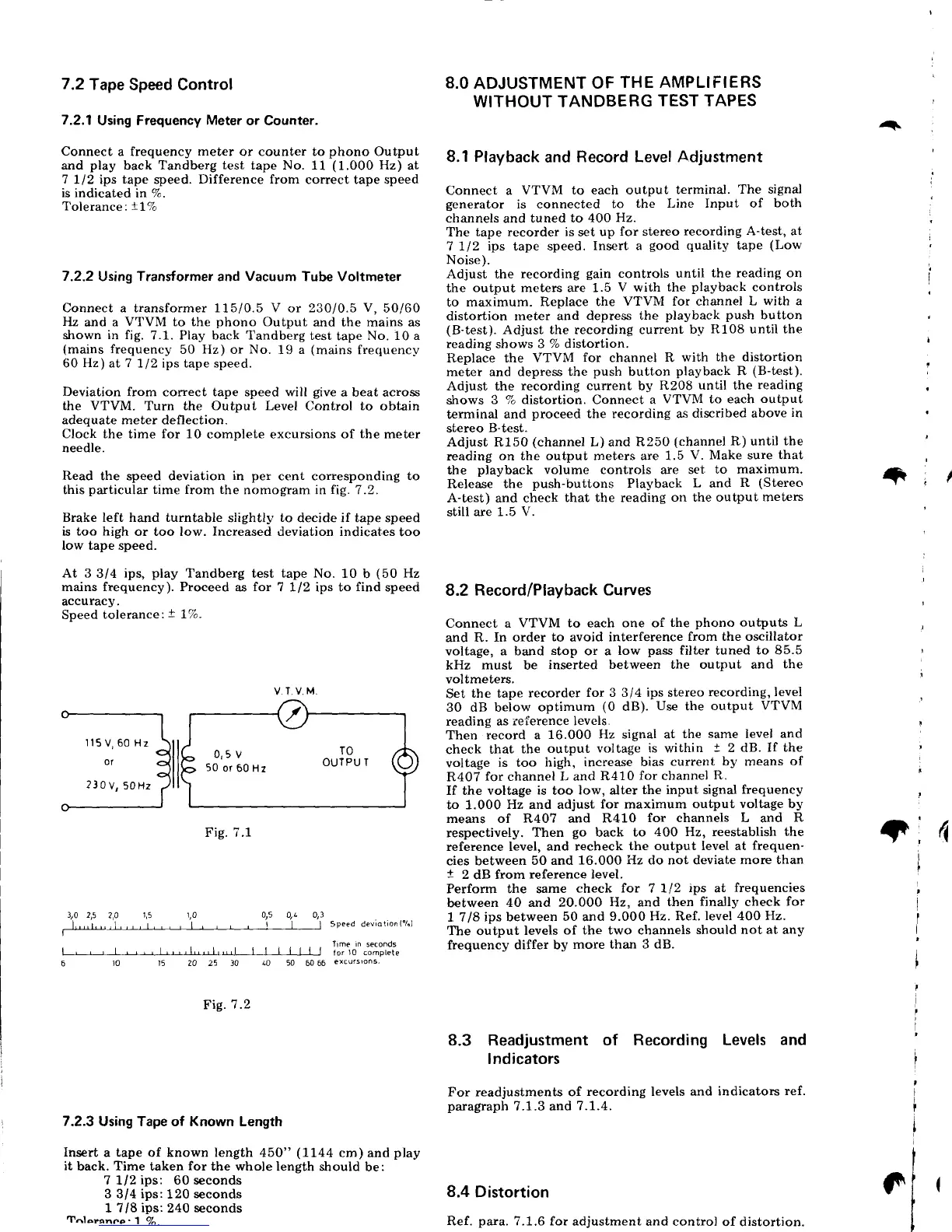
Connect a transformer 115/0.5 V
or
230/0.5
V,
50/60
Hz
and a
VTVM
to the
phono
Output
and the mains as
shown
in fig.
7.1. Play back Tandberg
test
tape
No. 10 a
(mains
frequency
50 Hz) or
No.
19
a
(mains
frequency
60
Hz)
at
7
712 ips tape speed.
Deviation
from correct tape speed will
give
a beat across
the VTVM.
Turn the
Output
Level Control
to
obtain
adequate meter
deflection.
Clock
the time
for
10 comolete excursions of
the
meter
needle.
Read
the speed deviation
in
per
cent corresponding to
this
particular
time from the
nomogram in
|ig.7.2.
Brake left hand turntable
slightly
to
decide if tape speed
is
too high
or too low. Increased deviation indicates
too
low tape speed.
At 3314 ips,
play
Tandberg
test
tape
No. 10
b
(50
Hz
mains frequency). Proceed
as
for
7 1/2 ips to
find
speed
accuracy.
Speed
tolerance:t
l7o"
Fig.7.1
,0
2,5
2,A
1,5
r,0
0,5
gL
0/3
1,.,,r.,,1,,,,1,,
, l,
, , ,
I
I I
SPeeddeviotion('A)
I
hme
rn
seconds
.,,J
I
I
I
|
|
|
|
torr0
complete
l0
40 50
60 66
excursrons-
F\9.7
.2
7.2.3
Using Tape of Known Length
Insert
a
tape of known length
450"
(1144
cm) and
play
it
back. Time taken
for
the whole
length strould
be:
7
1/2
ips:
60 seconds
3
3/4
ips:120 seconds
1 7/8
ips:240 seconds
Tnloranne
. 'l
7^
8.0
ADJUSTMENT
OF
THE AMPLIFIERS
WITHOUT TANDBERG
TEST TAPES
8.1
Playback
and
Record Level Adjustment
Connect a
VTVM to each output
terminal.
The signal
generator
is connected
to
the Line Input of
both
channels and tuned
to 400
Hz.
The
tape recorder is
set
up
for
stereo
recording A-test, at
7
112 ips
tape
speed.
Insert a
good
quality
tape
(Low
Noise).
Adjust the
recording
gain
controls until
the reading on
the
output meters are 1.5
V with
the
playback
controls
to
maximum. Replace
the
VTVM for channel
L with a
distortion rneter
and depress the
playback
push
button
(B-test).
Adjust the recording current
by
R108
until
the
reading
shows
3 % distortion.
Replace the
VTVM for channel R
with
the distortion
meter and depress the
push
button
playback
R
(B-test).
Adjust the
recording current
by
R208 until the
reading
shows
3 % distortion. Connect a
VTVM to each
output
terminal
and
proceed
the recording as
discribed above
in
stereo
B-test"
Adjust R150
(channet
L) and R250
(channel
R) until
the
reading
on the output meters are 1.5
V. Make sure that
the
playback
volume controls ate set
to maximum.
Release
the
push-buttons
Playback
L
and
R
(Stereo
A-test) and check
that the reading
on the output
meters
still are 1.5 V.
8.2 Record/Playback
Curves
Connect a
VTVM to
each
one of
the
phono
outputs L
and R.
In order
to
avoid
interference
from the oscillator
voltage,
a band
stop
or a
low
pass
filter
tuned
to 85.5
kHz must be
inserted
between the output and
the
voltmeters.
Set
the tape
recorder
for 3 314
ips
stereo
recording, level
30 dB below
optimum
(0
dB).
Use
the
output
VTVM
reading as
reference levels.
Then
record a
16.000
Hz signal at
the
same
level and
check
that
the
output
voltage is within
!
2 dB.
If the
voltage
is too
high, increase
bias
current by means
of
R407
for
channel
L
and
R410
for
channel
R.
If the voltage
is
too
low, alter
the input signal frequency
to 1.000
Hz and adjust
for maximum output
voltage by
means of R407 and
R410
for channels L
and
R
respectively.
Then
go
back
to
400 Hz, reestablish the
reference level,
and recheck
the output level at
frequen'
cies between
50 and
16.000 Hz do not deviate
more than
t
2
dB
from
reference level.
Perform the same
check
for
7
112
tps
at
frequencies
between
40 and 20.000
Hz, and
then finally check
for
1 7/8
ips between
50
and
9.000
Hz. Ref.
level
4OO
Hz.
the output
levels
of the two channels
should not at any
frequency
differ by
more than
3 dB.
8.3
Readjustment
of Recording
Levels and
Indicators
For readjustments of
recording levels and
indicators
ref.
paragraph
7.1.3 and
?.1.4.
8.4
Distortion
Ref.
para.
7.1.6 for
adjustment and control
of distortion.
^+
I
I
+,1
i
4
20 25
'l
n
(
rr
lU
-:'-
'
nr rreu
I
50
or
60 Hz
115
V) 60 Hz
230V,50H2
 Loading...